Development of Lightweight Carbon-Fiber Mirrors for the RICH 1 Detector of LHCb
G.J. Barber a, A. Braem b, N.H. Brook c, W. Cameron a, C. D’Ambrosio b, N. Harnew d,
J. Imong c, K. Lessnoff c, R.N. Martin e, F.C.D. Metlica c,∗, R.C. Romeo e, D. Websdale a
aImperial College London, London, UK bCERN, Geneva, Switzerland cUniversity of Bristol, Bristol, UK dUniversity of Oxford, Oxford, UK
eComposite Mirror Applications, Inc., Tucson, AZ, USA
Abstract
The design, manufacture and characterization of lightweight carbon-fiber spherical converging mirrors for the RICH 1 Cherenkov detector of the LHCb experiment at CERN are described. The mirrors need to be lightweight to minimize the material for traversing particles and fluorocarbon-compatible to avoid degradation in the C4F10 gas radiator of RICH 1. Four large-sized carbon-fiber mirrors covering a total surface area of ∼2 m2 were installed in RICH 1 in July 2007. The mirrors have a radius of curvature of ∼2700 mm, a high reflectivity of ∼90% in the 200-600 nm wavelength band, a low areal density of ∼5 kg/m2 equivalent to ∼1.2% of a radiation length. Results of the radiation and fluorocarbon testing of the mirror prototypes are also reported.
Key words: carbon-fiber mirrors, RICH, LHCb, lightweight mirrors, CFRP
PACS: 29.40.Ka, 42.79.Bh
The LHCb experiment [1], [2] is a dedicated second generation B-physics experiment to study CP violation and to search for rare B decays at the CERN Large Hadron Collider (LHC) in Geneva, Switzerland. The experiment has a Ring Imaging Cherenkov (RICH) detector system [3], that will provide powerful particle identification. The RICH detector system comprises two detectors, RICH 1 and RICH 2, covering the momentum range from .1 GeV/c up to and beyond 100 GeV/c. In RICH 1 [4], the focusing of Cherenkov light onto the pho.ton detectors is accomplished using a combination of spherical converging mirrors which lie within the detector acceptance and secondary planar mirrors 1 positioned outside the detector acceptance, shown in Fig. 1. The spherical mirrors must be lightweight to minimize the amount of material in the path of the traversing particles and must be compatible with the radiation environment of RICH 1 and the C4 F10 fluorocarbon gas which is used as the Cherenkov radiator.
Corresponding author. Email address: Fabio.Metlica@cern.ch (F.C.D. Metlica).
Over the last several years [5] starting from 1998 two lightweight mirror technologies were tested for the RICH 1 spherical mirrors: glass-coated beryl.lium [6] and composite mirror structures. Two types of composite mirrors were studied. The first, polymethyl-metacrylate based, was manufactured in-house [7], while the second, CFRP(carbon-fiber.reinforced-polymer), was manufactured by CMA 2 . Both glass-coated beryllium and CFRP proved to be suitable for the RICH 1 spherical mirrors [8]. The CFRP technology was chosen for RICH 1, being the most promising, but also on grounds of delivery time and cost. Extensive R&D of the CFRP tech.nology at CMA in collaboration with LHCb lead to the production of four large spherical mirrors for RICH 1, each .835 mm . 640 mm. The R&D and mirror production is the subject of this paper.
1 The planar mirrors are made of Simax borosilicate glass.

Fig. 1. Side view of the RICH 1 detector showing the plane and spherical mirror arrangement.
The spherical mirrors lie within the detector acceptance, i.e. ±25 mrad to ±250 mrad (vertical) and ±25 mrad to ±300 mrad (horizontal). The LHCb interaction point (IP) is shown at the left.
2. Mirror Requirements
The three important parameters defining the op.tical quality of a mirror are the average geometrical quality D. , the radius of curvature R and the reflec.tivity. The parameter D. is defined as the diameter of the circle at the mirror centre of curvature (CoC) which contains 95% of the reflected light intensity from a point source placed at the CoC. The setup for the D. , R [9], [10], and reflectivity measurements are described in the Appendix, giving precisions of .D. .0.06 mm, .R.4 mm and .ref l.1.5%, respec.tively. The mirror requirements are listed below.
Composite Mirror Applications, Inc., Tucson, AZ, USA; www.compositemirrors.com
Lightweight: the total mirror material lying in the detector acceptance, i.e. in the path of the crossing particles, must have a radiation length less than 2%X0 and a nuclear interaction length less than 1%.I , equivalent to a CFRP areal density 3 less than 8.5 kg/m2 .
Radiation tolerant: the mirror properties must not be a.ected by radiation up to a 10 kGy ab.sorbed dose, equivalent to ten years (expected life.time of LHCb) in the radiation environment of RICH 1. This is especially important for the mir.ror section closest to the LHCb beampipe where radiation is highest.
Fluorocarbon compatibility: the mirror proper.ties must not degrade in the C4 F10 fluorocarbon gas-radiator environment. An exposure time of approximately ten years to C4 F10 without any no.ticeable degradation is highly desirable. Acceler.ated ageing has not been undertaken due to un.certainties in the acceleration factor, see section 3.
Optical quality: the mirrors must satisfy the following optical specifications: D. <2.5 mm, R=2700(±1%·R) mm, and an average reflectivity of .90% in the 200 nm≤ . ≤ 600 nm wave.length band. In particular the reflectivity must be >70% for 200 nm≤ . ≤250 nm and >85% for 250 nm≤ . ≤600 nm for an average angle of photon incidence of 25.
Structural rigidity: the mirror must have neg.ligible deformation under its own weight when mounted onto the support frame which is located outside the detector acceptance.
Dimensions: four mirrors each of size . 835 mm . 640 mm, are required to cover the RICH 1 optical acceptance of .2 m . Two larger mirrors can not be used because of the beampipe which lies at the RICH 1 centre.
Non-ferromagnetic: the mirrors must be insensitive to the residual magnetic field of .60 mT in the RICH 1 region from the LHCb dipole magnet.
3. Testing of Prototype Samples
An R&D program at CMA, in close collaboration with LHCb, was undertaken to verify the feasibility of the lightweight CFRP technology in a radiation and fluorocarbon environment. A set of CFRP prototypes was manufactured by CMA during the first half of 2006 for testing at CERN.
3 Mass per unit surface area of mirror.


Fig. 2. Photographs of the CMA prototypes: a) the demonstration mirror, b) the two small spherical mirrors, and c) one of the three flat CFRP samples.
The CMA samples were made of the same CFRP material as for the final RICH 1 mirrors. The CFRP material was specifically chosen from a large variety to meet the RICH 1 requirements. The materials used in the manufacture of the mirrors were: for the carbon-fibers, Toray M46J PAN; for the matrix, EX-1515 cyanate ester resin from Bryte Technologies; and for the adhesive, Huntsman 1210 A/B and Huntsman 420 A/B. Photographs of the samples are shown in Fig. 2, and the details are listed below.
Demonstration mirror: a 600 mm . 600 mm . 33 mm square-shaped mirror with a nominal radius of curvature R=2200 mm, areal density of .5 kg/m2 and an Al(70 nm)+SiO(70 nm) reflective coating 4 . This mirror is a smaller version of the final mirrors and serves to demonstrate the de.sign concept. It is a two CFRP skin 5 honeycomb design with core cell reinforcement (see sections 4 and 5), manufactured from an existing mandrel available at CMA. This mirror was used only for fluorocarbon testing and was not exposed to radiation.
Two small spherical mirrors: each mirror is 150 mm in diameter (reflective area) and is 30 mm thick. The nominal radius of curvature is R=1890 mm, the areal density is .5 kg/m2 , and the reflective coating is Al(70 nm)+SiO(70 nm). The mirrors consist of two CFRP skins with six radial spokes placed in-between the skins and en.closed in CFRP. The mirrors are named M1 (used only for fluorocarbon testing) and M2 (used only for radiation testing), respectively.
Three flat CFRP samples: each of dimensions .95 mm . 105 mm . 0.6 mm with a weight of .8.8 g, and used in mechanical tests. These samples consist of eight pre-impregnated CFRP sheets laid and glued one on top of the other at four orientation angles [0. /45./-45./90.]. The surface is raw without any optical quality surface finish to allow an application of a reflective coat.ing. The samples are named F1 (used only for fluorocarbon testing), F2 (used only for radiation testing), and F3 (used only for the CERN fire safety testing), respectively.
4 An aluminium layer protected by a silicon monoxide layer is the standard CMA reflective coating.
5 Several sheets of CFRP at di.erent orientation angles glued together to form a single CFRP layer, is called a skin.
The optical and mechanical properties of all samples were first measured upon their arrival at CERN in May 2006 and then were exposed either to radiation or C4 F10 but not to both at the same time, and measured again at regular intervals. C4 F10 gas ex.posed to radiation can give rise to the formation of HF acid in the presence of water vapor (H2 O), but this will be avoided in RICH 1 by circulating and purifying the C4 F10 gas radiator, and by keeping the H2 O contamination at a low level, .100 ppm.
The measured optical parameters of the mirror prototypes were D. , R and reflectivity. In addition, the mechanical properties of the flat samples were measured: surface roughness, tensile rigidity (pulling), flexural rigidity (bending), weight and physical dimensions.
The fluorocarbon compatibility testing consisted of keeping three samples (demonstration mirror, mirror M1, flat F1) in a gas-tight tank which was first pumped under vacuum and then filled with C4 F10 gas at room temperature and .5 kPa overpressure with respect to atmospheric pressure to minimize any air from leaking into the tank. The samples were kept in the tank for a total of .17 months and taken out at regular intervals for measurement. Accelerated ageing by increasing the temperature or pressure of C4 F10 in the tank was not undertaken because of uncertainty in the acceleration factor to be applied, and therefore in interpreting the results.
Table 1 The D. , R of the CMA prototype mirrors for di.erent degrees of exposure to C4 F10 gas and radiation. The precisions of the D. , R measurements are .D. .0.06 mm and .R.4 mm, respectively.

The two other samples, mirror M2 and flat F2, were exposed to radiation in three 80 steps with a total absorbed dose of 1 kGy, 4 kGy 70 and 10 kGy, respectively. The irradiation took place at the IONISOS cobalt-60 gamma facility 6.
As a result of the above tests, no significant change was measured in the properties of the samples after 40 17 months exposure 7 to C4 F10 or a 10 kGy total 30 absorbed dose. The results of the testing are summarized below.
D. and R: the measured D. , R for different degrees of exposure is shown in Table 1. Mirrors M1 and M2 have D. .0.8 mm and R.1890 mm, while the demonstrator mirror has D. .1.1 mm and R.2205 mm. The difference in the measured. values are caused by small internal alterations and movements of the mirror structure over time due to changes in the ambient conditions (temperature, pressure and humidity) and by minor 60 stresses applied to the mirror during measurement 50 when supported by the optics stand. The differences in R are within their systematic errors. The 30 demonstrator mirror arrived later at CERN and 20 has therefore one month less exposure. M2 was remeasured fifteen months after the completion of the irradiation tests as a check for any aging while being stored exposed to air in normal laboratory ambient conditions.
Reflectivity: the wavelength dependence of the reflectivity for mirrors M1 and M1 as function of exposure is shown in Fig. 3.
6 IONISOS, Dagneux, France; www.ionisos.fr.
7 Exposure to C4 F10 gas will continue for at least another year with biannual measurements.
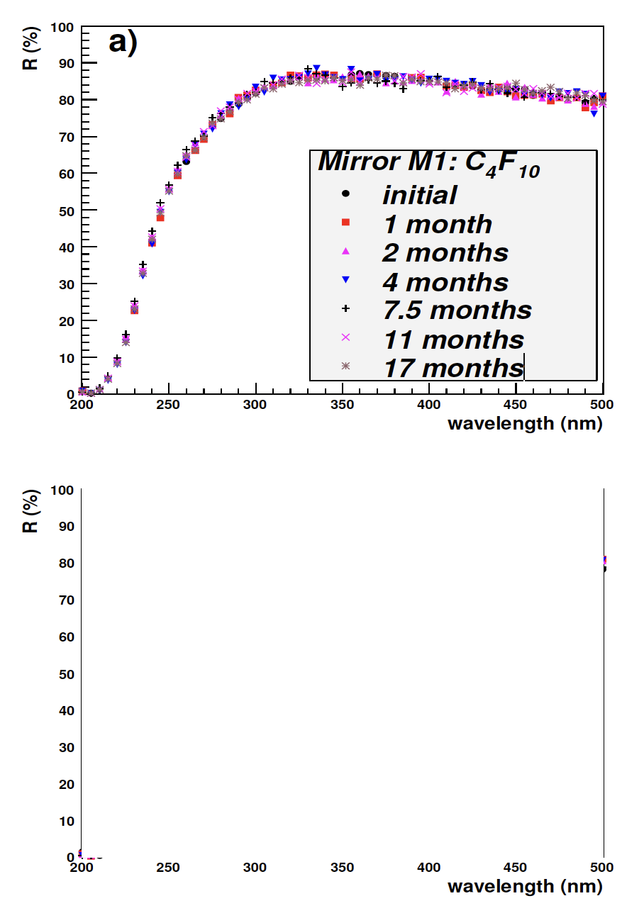
Fig. 3. Reflectivity curves of mirrors M1 and M2 for different levels of exposure to a) C4 F10 and b) radiation, respectively. The reflectivity for mirror M2 after 15 months from its final irradiation is also shown. The precision of the reflectivity measurement is .ref l.1.5%.
The curves are unchanged within the errors (.ref l.1.5%). The standard CMA coating Al(70 nm)+SiO(70 nm) gives a low reflectivity in the UV range. The reflectivity of the demonstrator mirror was not measured because it did not fit into any of the available reflectometers.
Surface roughness: the surfaces of the flat samples are raw and have not been processed to have an optical quality surface finish. The average surface roughness 8 , Ra, of the flat samples F1 and F2 is .1.8 µm, shown in Fig. 4. There is no noticeable change within the errors. The surface roughness of F2 was also measured five and fifteen months after completing the irradiation testing as a check for any natural ageing, these results are also shown in Fig. 4.
Mechanical properties: mechanical tests give an average tensile rigidity of .8000 N/mm and a flexural rigidity of .33 N/mm for flat samples F1 and F2 and remain unchanged over the testing period. Photographs of the setup 9 for these tests are shown in Fig. 5.
Weight, dimensions and structure: the weight and dimensions of the flat samples F1 and F2 remain unchanged to within the errors (.10 mg, .0.01 mm, respectively). Comparison of photographs taken with a stereo-microscope 10 at magnifications of 10. and 100. of the F1 and F2 surfaces show no change in structure.
The third flat sample (F3) was used for a CERN safety test which is required for all combustible materials installed in the LHC experimental areas. An x-ray spectrometer analysis proved that the CFRP sample is halogen and sulphur free as expected. Sample F3 passed the CERN fire test, i.e. when it was ex.posed to a small fire source for .1 minute it burned producing black smoke but the flame was not propagated along the CFRP. The chosen CFRP material therefore fulfills all the CERN safety requirements and can be used freely in the LHC experiment halls.
4. Mirror Design
Each RICH 1 spherical mirror has a sandwich hon.eycomb structure, consisting of two outer CFRP skins, each 1.5 mm thick, with core cells lying in between the skins as reinforcement, see section 5. Each mirror has a size of .835 mm . 640 mm, a thickness of 33 mm, R=2700 mm, and an areal den.sity of .5 kg/m2 (.1.2%X0). This design provides for a lightweight and rigid mirror structure.
8 Ra is the arithmetic average of surface roughness; Veeco NT3300 Optical Profiler used to measure roughness.
9 UTS Machine, from United Testing Systems. 10 LEICA MZ16

Fig. 4. Surface roughness (Ra) measurements of the flat samples: top scale, F2 radiation exposure in kGy; and bottom scale, F1 C4 F10 exposure in months. There are also two measurements for F2 at 5 and 15 months after its irradiation.

Fig. 5. Photographs of the mechanical testing setup of a CFRP flat sample, a) tensile (pulling) testing, and b) flexural (bending) testing.
The design of the RICH 1 spherical mirror assem.bly consists of four CFRP rectangular mirrors sup.ported by a CFRP mounting frame. The two top (bottom) mirrors are paired together forming one spherical surface pointing to the same top (bottom) centre of curvature (CoC). The CFRP frame con.sists of two C-like halves joined at the centre bottom and top respectively, shown in Fig. 6.
Each mirror is supported at three points on the outer mirror corners, which lie outside the detector acceptance. The circular cut-out at the centre of the mirrors is for the LHCb beampipe and the cut-out has a radius of 61 mm. The gaps between the mirror sides are 3 mm.

Fig. 6. A rear view CAD design of the CFRP assembly. Its size is .1.7 m . 1.5 m. The positions of the three mirror mounting points are shown for the bottom right mirror. Mounting point 1 is the pivot and the other two points (2, 3) provide for mirror tip-tilt adjustment about point 1. The C-halves of the support frame are joined at the bottom centre (point 1) and similarly at the top.
To verify the design concept, FEA 11 studies have been undertaken for the mirrors supported onto the CFRP frame and aligned to their respective CoC. The maximum mirror deflection due to gravity is for the mirror area closest to the beampipe cut.out at a position furthest away from the mounting points. The mirror deflection is minimal, .3.5 µm, see Fig. 7. The FEA for the other three mirrors mounted onto the frame give symmetrically the same results. The lowest mirror resonant frequen.cies are relatively high (&160 Hz) and these do not pose a problem for our applications.
5. Mirror Manufacture
The mirror manufacturing was performed at CMA in 2006 using an optical replication process [11], [12], [13]. A mirror manufactured using this process is called a replica mirror. The materials used are given in section 3.
A convex borosilicate (Pyrex) glass mandrel matching the CFRP coe.cient of thermal expan.sion, polished to the required optical precision of .1-2 nm rms micro-surface roughness, was used for the surface replication. The grinding and polishing of the glass blank 12 was carried out at CMA 13 us.ing classical optical methods, and the final polished surface was checked with a spherometer. The polished mandrel has a convex surface with a 2700 mm radius of curvature and a 1100 mm diameter.
11 Finite Element Analysis, designed using SolidWorks and studied using COSMOS software. 12 Fabricated by Hextek Corporation, Tucson, AZ, USA; www.hextek.com. 13 By R. F. Royce of Royce Optical; www.rfroyce.com.

Fig. 7. FEA mirror deflection contour plot for a mirror sup.ported onto the CFRP frame and aligned to its CoC (top mirror rear view). The maximum mirror deflection due to gravity is at the beampipe circular cut-out and is .3.5 µm. The arrow indicates the gravity direction. The average de.flection values due to gravity, across the mirror surface are given. The supporting edges of the mirror, which have the three mounting points attached are top and right in the plot, respectively.
The CFRP material comes in tape form on a roll, called prepreg, i.e. the carbon-fibers are pre.impregnated with a cyanate ester resin (matrix). The tape is a few 100 µm thick, and the carbon-fibers are unidirectional and uniformly spread in the matrix. The prepreg consists of .2/3 carbon-fibers which are the reinforcement material and .1/3 resin which is the matrix material that binds the fibers together. Several prepreg sheets are laid over the polished mandrel and glued together in fixed orientations resulting in a quasi-isotropic CFRP front skin 1.5 mm thick, shown in Fig. 8. The front skin hardens taking the shape of the mandrel by curing at .121 . C in a vacuum. Then the core structure (described below) and back skin are glued onto the front skin and cured. The hon.eycomb mirror is then separated from the mandrel and is ready to be vacuum-coated with a reflective film. The replication process accurately reproduces the mandrel polished surface onto the mirror. The front surface of the replicated mirror needs only to be appropriately cleaned, no polishing is required. A large number of replica mirrors, typically up to 40-50, can be produced from a mandrel before the mandrel needs refiguring.
The core cell structure consists principally of applied. The circular beampipe cut-out cylindrical cells, 50 mm in diameter and 30 mm in length, covering nearly all the CFRP skin surface. Square cells, 25 mm . 25 mm . 30 mm, line the two mirror supporting edges to ensure higher sti..ness. The thickness of the core cell wall is 0.5 mm and small holes allow for venting the honeycomb structure.

Fig. 8. Stages of mirror fabrication: a) laying of CFRP sheets onto the glass mandrel; b) laying the core structure on top of the front skin; c) laying the top skin onto the core structure; d) the completed mirror (Mirror-3) with the reflective coating applied. The circular beampipe cut-out is visible in c) and d).
CFRP tabs are glued onto the back skin in cor.respondence to the three mounting points on the two mirror supporting edges. The CFRP mounting frame has a square tubular structure and is made of the same material as the mirrors. The complete as.sembly consisting of the frame and the four mirrors, shown in Fig. 9, weighs .17 kg. The CFRP assem.bly fabrication was completed at CMA in January 2007 and then delivered to CERN. The reflective coating was performed afterwards by another optics company, see section 6.
6. Mirror Coating
CMA’s standard reflective coating is aluminium protected by silicon monoxide (Al+SiO). It is used for astronomy applications providing good reflectivity in the visible range but not in the UV, see Fig. 3. An aluminium and magnesium fluoride (Al+MgF2 ) coating which provides for high reflectivity also in the UV was chosen for RICH 1. This coating, which has a simpler coating procedure, was preferred to an Al+SiO2 +HfO2 coating [14] as used for the RICH glass mirrors of LHCb 14 . CMA started developing the Al+MgF2 coating technique achieving good results, but unfortunately not in time to meet the tight schedule of the RICH 1 mirror installation.
14 The RICH 1 planar mirrors and all the RICH 2 mirrors are made of Simax glass. These mirrors have a smaller mirror diagonal and have been coated at CERN.
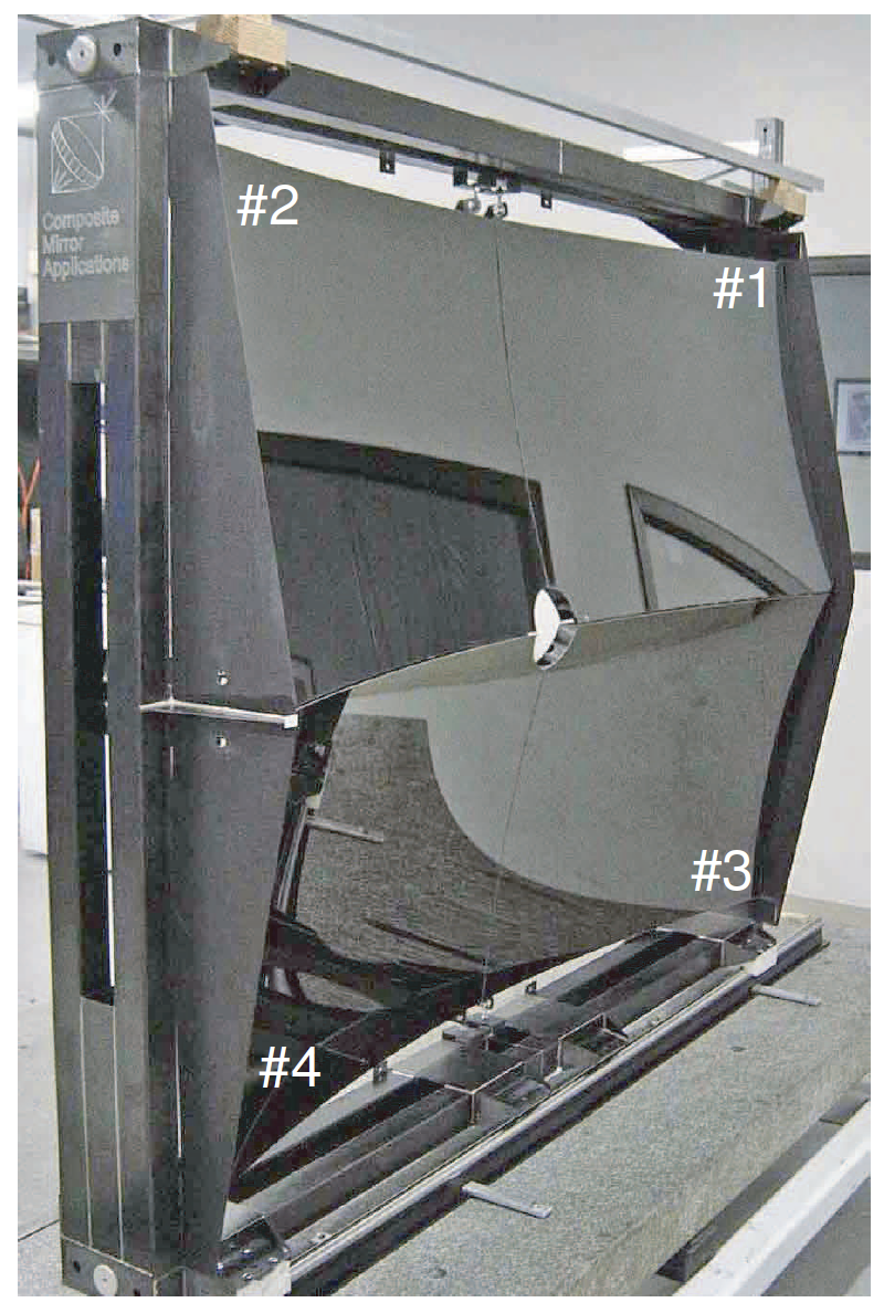
Fig. 9. Completed CFRP assembly at CMA in January 2007. The mirrors are uncoated in this photograph. The mirrors are labeled 1 to 4.
The CFRP mirror coating was performed at SESO 15 in March 2007. SESO has developed the technology of aluminium-protected coatings for UV applications [15] and has successfully coated down to the UV range for previous RICH applications [16]. Furthermore it possesses a large enough coating chamber 16 to accommodate the CFRP mirrors which have a large mirror diagonal of 1069 mm.
15 Societe Europeenne de Systemes Optiques, Aix-en-Provence, France; www.seso.com. 16 BALZERS SCS 1131, internal diameter of 1130 mm.

Fig. 10. Simulated reflectivity curves for varying thicknesses of MgF2 films protecting an Al(80 nm) film. Variations in reflectivity are caused by interference effects in the MgF2 film.
The reflectivity of the aluminium film in a given wavelength band can be enhanced by exploiting interference effects in thin films, by selecting the appropriate thickness of the MgF2 protection film. The MgF2 film thickness was optimized to give highest reflectivity in the wavelength band ∼250-350 nm. This matches the quantum efficiency of the LHCb RICH photon detector [17] which peaks at ∼270 nm. MgF2 films thinner than 80 nm give a lower reflectivity, a simulation 17 of which is shown in Fig. 10.
During the coating process, tools which ensure a uniform film thickness across the mirror surface were not employed because they are costly and require time to develop. The geometrical setup of the mirror in the chamber was such that, without uniformity tooling, the evaporated film thickness decreased across the mirror, being thickest at the centre and thinning down by ∼40-50% at the mirror farthest edge. The applied coating consists of a 30 nm chromium adherence layer to ensure adhesion between the mirror CFRP surface and an 80 nm aluminium reflectance layer, and on top a 160 nm MgF2 protection layer, at the mirror centre, i.e. Cr(30 nm)+Al(80 nm)+MgF2 (160 nm). The simulation shows that the expected reflectivity across the mirror surface is always &85% at 270 nm, demonstrated in Fig. 11.
17 Simulation by CERN and SESO using FilmStar and Macleod software.
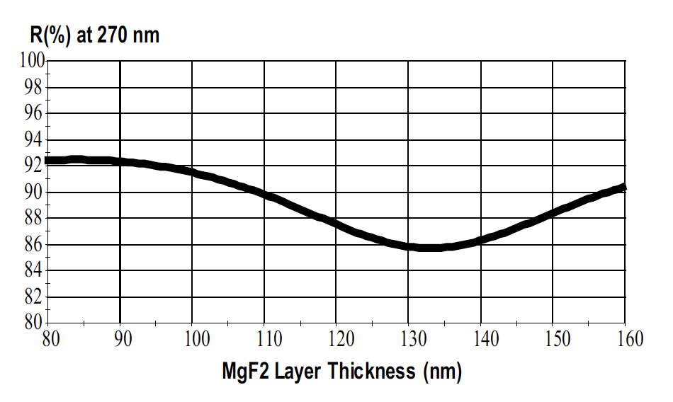
Fig. 11. A simulation of the reflectivity at 270 nm as function of MgF2 thickness, decreasing from 160 nm at the mirror centre to 80 nm at its periphery.
Witness samples to check for contamination were left overnight in the presence of CFRP samples in the coating chamber under vacuum and then analyzed 18 . Out-gassing and contamination arising from the CFRP material was found to be completely negligible. The temperature in the coating chamber during the evaporation process was ∼30 ◦ C, which is not a concern for the CFRP structure.
A successful preliminary coating run was performed at SESO to verify the procedure and resulting reflectivity, by placing CFRP and glass samples 19 at increasing radial distances from the coating chamber centre. Results are shown in Fig. 12a. The wide peak of the reflectivity curves at ∼450 nm in Fig. 12a move to shorter wavelengths (∼300 nm and ∼350 nm) as the radial distance increases (i.e. MgF2 thickness decreases), as expected by the simulation of Fig. 10. The simulation curves for MgF2 (160 nm) and MgF2 (100 nm) describe reasonably well the coated samples close to the chamber centre and at the periphery respectively, indicating that the MgF2 film thickness is ∼160 nm in the central region, thinning down to ∼100 nm at the periphery, as expected.
A witness sample was placed in the chamber during the coating of each mirror, located next to the mirror longer edge at a radial distance of 320 mm from the chamber centre. The simulation curve Al(80 nm)+MgF2 (120 nm) satisfactorily describes the witness sample reflectivity curves, shown in Fig. 12b.
18 Analyzed using infrared spectroscopy by INTESPACE, Toulouse, France; www.intespace.fr. 19 A previous coating test (Al+MgF2 ) at CERN showed no difference in reflectivity curves when using glass or CFRP samples.

Fig. 12. a) Preliminary coating run: reflectivity curves for six samples placed at increasing radial distance from the centre of the coating chamber, from 20 mm to 470 mm. b) Coating run: reflectivity curves of the witness samples, each mirror has one witness sample. The simulation curves, labeled Sim, are for comparison. The precision of the reflectivity measurement is σref l∼1.5%.
The average reflectivity across the entire mirror surface is ∼90% and is &85% over the 200 nm to 600 nm range. A photograph of a SESO-coated CFRP mirror is shown in Fig. 8d and the CFRP coated mirror assembly is shown in Fig. 15.
7. Mirror Characterization
On visual inspection the uncoated mirrors had a good optical surface finish. The Ronchi and the Shack-Hartman wavefront sensor tests [12] were performed at CMA. The Ronchi test is qualitative and is used to determine the mirror sphericity. The Ronchi lines for the mirror assembly are reasonably straight indicating a good spherical surface, demonstrated in Fig. 13.

Fig. 13. Ronchigram of a bottom mirror (Mirror-4). The circles are from the core structure, i.e. core print-through [12]. The circles can be seen in the photograph located along the interference bands. The print-through is small and has no adverse effect on the D◦ .
The Shack-Hartman 20 test gives a ∼2.5 μm peak to-valley 21 (P-V) deviation from a sphere with an RMS∼0.5 μm, at λ=635 nm. The print-through of the core on the surface is .1 μm. The micro-surface roughness is ∼1.5nmrms 22.
20 Shack-Hartman HASO 32, 635 nm laser. 21 P-V (peak-to-valley) is the difference between the highest and lowest surface deviations, and RMS is the root mean square of the surface deviations. 22 Measured with a Wyko Topo 3-D optical surface profiler.
The D◦ and R of the mirrors were measured before and after the coating, listed in Table 2. Before the coating the measured D◦ was ∼0.6 mm (February 2007) but this increased to ∼1.2 mm (June 2007) after the coating 23 . This is attributed to the stresses applied onto the mirrors during the coating procedure. The radius of curvature R is ∼2710 mm and did not change within errors. The D◦ , R plots and the D◦ spot for Mirror-1 is shown in Fig. 14; these are typical for all four mirrors.
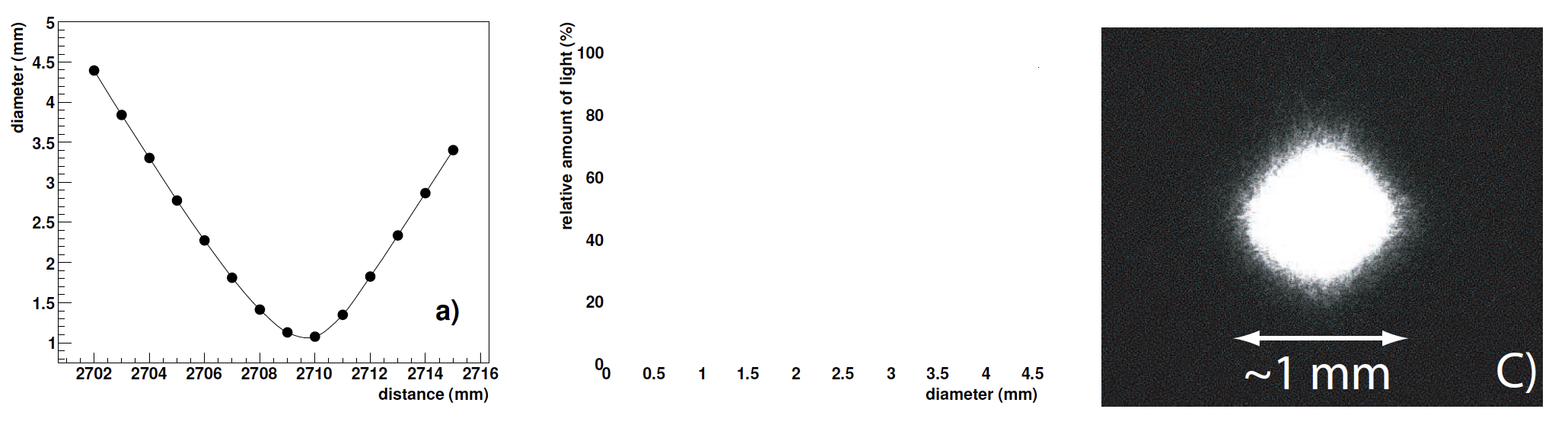
Fig. 14. D◦ and R measurements for Mirror-1 taken in June 2007 (see the Appendix for information on the D◦ and R measurement method). a) Spot size as function of the distance of the mirror from the CCD camera, the minimum is at R=2710 mm. b) The relative amount of light (%) as function of the circle diameter for the smallest spot; 95% of the light is contained by a circle 1.07 mm in diameter, i.e. D◦ =1.07 mm. c) Photograph of the smallest spot which is obtained at the mirror centre of curvature, i.e. at R=2710 mm with D◦ =1.07 mm.
Table 3 Average parameters of the four CFRP mirrors.
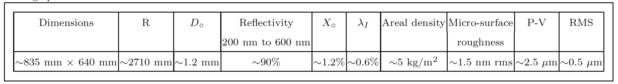
Table 2 The D◦ and R of the four CFRP mirrors before (February 2007) and after the coating (June 2007). The precisions of the D◦ , R measurements are σD◦ ∼0.06 mm and σR∼4 mm, respectively.

A summary of the average mirror parameters is given in Table 3. All four mirrors are well within the RICH 1 specifications.
23 The D◦ is well below the specification of <2.5 mm.
8. Alignment and Installation
After coating, the mirrors were mounted onto the CFRP frame and aligned in a laboratory at CERN. The alignment was done via survey with a precision of ∼0.1 mrad. The survey located the top and bottom CoC positions on two optical benches. A laser source and screen were mounted onto each optical bench close to the CoC. The laser uniformly illuminated the two top mirrors which were aligned by pointing the two reflected light spots (one spot per mirror) onto the CoC point on the screen. The same was done for the two bottom mirrors. The combined spot size of the aligned top (bottom) mirrors was ∼1.5 mm.
After completing the mirror alignment, the two C-halves were opened and closed several times to study the alignment reproducibility of the mirror assembly, which was found to be ∼0.5 mrad, with respect to the CoC. The stability of the alignment was monitored for one week by two PC-controlled cameras. Photographs of the combined spot at the CoC of the two top (bottom) mirrors were taken at regular time intervals. After an initial relaxation of the newly aligned mirrors of about one day, the alignment remained stable over the rest of the one week monitoring period, and was found to be ∼ 0.05 mrad, with respect to the CoC. The mirror alignment reproducibility and stability are well within the RICH 1 requirements of .1 mrad.

Fig. 15. Photograph of the CFRP mirror assembly (on the left), installed in RICH 1, in the LHCb experiment underground hall. The beryllium beampipe passes through the centre and the planar glass mirror arrays (top and bottom) are on the right.
The CFRP mirror assembly was successfully installed in RICH 1 in the LHCb underground cavern in July 2007, shown in Fig. 15.
9. Summary
The carbon-fiber-reinforced-polymer (CFRP) light-weight mirror technology has been successfully developed for the RICH 1 spherical mirrors of the LHCb experiment at CERN.
No significant change was observed in the optomechanical properties of the CFRP prototype mirror samples after exposure to either radiation or C4 F10 fluorocarbon gas. A 17 month exposure to C4 F10 at ambient temperature and pressure, and 10 kGy total absorbed dose equivalent to ∼10 years in the RICH 1 radiation environment were accumulated. Exposure of the CMA prototype mirrors to C4 F10 gas with biannual measurements is continuing to further verify the long term compatibility.
Four large, ∼835 mm × 640 mm, CFRP spherical mirrors have been manufactured, covering a total surface area of about 2 m^2. They are of good optical quality and well within the RICH 1 requirements. The mirrors have a radius of curvature of ∼2700 mm, a high reflectivity of ∼90% in the 200600 nm wavelength range, and a low areal density of ∼5 kg/m2 , equivalent to ∼1.2%X0 and ∼0.6%λI .
The CFRP mirror assembly was installed in RICH 1 in the LHCb underground experimental hall in July 2007. First Cherenkov light onto the mirrors is expected in the second half of 2008, when the LHC is turned on and the LHCb experiment is going to take the first data.
Acknowledgements
We acknowledge the technical and infrastructure support from CERN in particular: O. Ullaland, W. Witzeling, C. Frei, D. Piedigrossi, E. Albrecht, and
C. David; J.J. Gayde and S. Berni of the CERN survey team; D. Pugnat of the CERN metrology team;
E. Barisone and A. Gerardin of the CERN mechanics testing team (MME-CERN); and S. Fumey of the LHCb-CERN installation team. We thank R. Head and T. Newbury (Bristol University, UK), and M. Brock (Oxford University, UK) for the engineering and mechanics support. We thank C. Cammarata,
B. Passier and J. Ferme of SESO (Aix-en-Provence, France) for fruitful discussions, and also for their availability and willingness to coat the mirrors on a short timescale. We also thank S. Rouif of the IONISOS irradiation centre at Dagneux-France.
Appendix
D◦ and R measurements The D◦ and R measurements of the mirrors are performed in an optical laboratory at CERN. The setup for the measurement of spherical converging mirrors is shown in Fig. 16.
The mirror is held by a three-point support system which is mounted on rails. A point-like source is obtained from a diode laser (λ=641 nm) connected 24 to an optical fiber. The laser and a CCD camera are fixed to a sliding table and move jointly along the line of the mirror axis. The sliding table is placed
24 DTA model HR400E with a KODAK sensor KAF-400E CCD; 16 bit, 9 μm . 9 μm pixel size, 6.9 mm . 4.6 mm sensor size.

Fig. 16. A schematic a) and photograph b) of the setup for the R and D◦ measurements of spherical converging mirrors. The photograph shows a small CMA prototype spherical mirror ready for measurement.
at a distance d from the mirror, corresponding to the approximate expected radius of curvature of the mirror. The point-like source uniformly illuminates the whole mirror surface and the reflected image (spot) is captured by the CCD camera. The measurements are automated. A LabVIEW 25 program controls both the CCD triggering and the movement of the sliding table using a stepping motor which has a 40 mm range. The sliding table moves in 1 mm steps, varying the distance d between the mirror and the laser light source. At each 1 mm step, the CCD takes a photograph of the spot image. At the end of the 40 mm scan, the LabVIEW program analyzes all the photographs and finds the smallest spot image using a centre of gravity method, from which the mirror R and D◦ are extracted.
25 LabVIEW (Laboratory Virtual Instrumentation Engineering Workbench) from National Instruments.
The radius of curvature R of the mirror is taken as the distance between the mirror reflective surface centre and the CCD sensor when the image spot size is a minimum. D◦ is the diameter of the circle which contains 95% of the light of the spot image of minimum size.
The precisions of the D◦ and R measurements are σD◦ ∼0.06 mm and σR∼4 mm, respectively. The D◦ for a given mirror can vary over time. The variation of the D◦ value is caused by very minor internal changes and movements of the mirror structure over time due to changes in the ambient conditions (temperature, pressure and humidity) and also by very small stresses applied to the mirror during its measurement when supported by the optics stand. The error on the R measurement is dominated by the systematic error in re-positioning the optical bench components for a given mirror measurement (the statistical error on R is ∼1 mm).
Reflectivity measurement The reflectivity is measured by two different reflectometers. The first is a commercial type, Perkin-Elmer Lambda 15 Spectrophotometer, for small samples typically with areal sizes up to ∼5 cm × 5 cm. The second is a CERN VUV 26 reflectometer built in house for larger samples up to ∼ 40 cm × 40 cm, shown in Fig. 17. The wavelength range and the photon incidence angle of the Perkin-Elmer are 200 nm to 600 nm (1 nm step) and ∼30◦ , respectively. While for the VUV the range and the photon incidence angle are 200-500 nm (5 nm step) and ∼5◦ , respectively. The precision of the reflectometers is σref l∼1.5%.
Referring to the schematic of the VUV reflectometer in Fig. 17, the intensity of the incident monochromatic light beam (Ii ) of diameter ∼4 mm and bandwidth ∼2 nm is first measured by photomultiplier PM2 by direct reflection from the rotating central mirror. After, the central mirror is rotated to allow a second reflection of the light beam from the centre of the measured mirror sample. The intensity of the reflected light beam (Ir ) is measured with photomultiplier PM2 which has a window diameter of 4 cm placed at ∼50 cm distance from the measured sample. The reflectivity is given by the ratio Ir /Ii. Photomultiplier PM1 is used for monitoring purposes. The reflectometer is operated using LabVIEW.
26 Very ultra-violet (VUV) reflectometer.

Fig. 17. A schematic a) and photograph b) of the CERN VUV reflectometer built in-house.
The average angle of incidence of the Cherenkov photons impinging onto the RICH 1 spherical mirrors is 25◦ . The two reflectometers measure the mirrors at different angels of incidence. Simulation studies 27 show that the difference in reflectivity between the RICH 1 photon incidence angle (25◦) and the reflectometers incidence angle (5◦ for the VUV and 30◦ for the Perkin-Elmer) is minimal and mostly within the precision of the reflectometers, as shown Fig. 18.
27 Simulation by CERN using FilmStar software.

Fig. 18. a) Simulation of the reflectivity as function of wavelength for two different photon angles of incidence, 5◦ and 25◦ . b) Simulation of the reflectivity as function of the photon angle of incidence for two different wavelengths, i.e. 270 nm and 450 nm. The coating is Al(80 nm)+MgF2 (160 nm).
References
[1] LHCb Collaboration, “LHCb reoptimized detector design and performance”, CERN/LHCC/2003-030, 2003.
[2] LHCb Collaboration, “The LHCb detector at LHC”, to be published in Journal of Instrumentation (JINST) in 2008.
[3] LHCb Collaboration, “LHCb RICH TDR”, CERN/LHCC/2000-0037, 2000.
[4] LHCb RICH group, LHCb Public Note, CERN-LHCb2004-121, Geneva, CERN, 20 Oct 2005, “LHCb RICH 1 Engineering Design Review Report”.
[5] C. D’Ambrosio, et al., Nucl. Instr. and Meth. A 478 (2002) 344, “Precision optical systems for the new generation of Ring Imaging Cherenkov detectors in high energy physics experiments”.
[6] G.J. Barber, et al., Nucl. Instr. and Meth. A 570 (2007) 565, “Glass-coated beryllium mirrors for the LHCb RICH 1 detector”.
[7] T. Bellunato, et al., Nucl. Instr. and Meth. A 538 (2005) 458, “Light composite mirrors for RICH detectors: production, characterisation and stability tests”.
[8] F. Metlica, to be published in 2008 in Nucl. Instr. and Meth. A, RICH 2007 Conference in Trieste-Italy, “Development of light-weight spherical mirrors for RICH detectors”.
[9] M. Laub, “Development of opto-mechanical tools and procedures for the new generation of RICH-detectors at CERN”, Ph.D. Thesis, LHCb 2001-130; Geneva, CERN.
[10] C. D’Ambrosio, et al., LHCb Public Note, LHCb-2000071, Geneva, CERN, 12 Apr 2001, “The optical systems of LHCb RICHes: a study on the mirror walls and mirrors specifications”.
[11] R. C. Romeo, et al., Opt. Eng. 39(09), 2320 (2000), “Advances in very lightweight composite mirror technology”.
[12] R. C. Romeo and R. N. Martin, Proc. SPIE Vol. 6273, 62730S (2006), ”Progress in 1m-class lightweight CFRP composite mirrors for the ULTRA telescope”.
[13] R. N. Martin et al., Proc. SPIE Vol. 6670, 667001 (2007), “Lightweight CFRP spherical mirrors for the LHCb RICH 1 detector”.
[14] A. Braem, et al., Nucl. Instr. and Meth. A 553 (2005) 182, “Metal multi-dielectric mirror coatings for Cherenkov detectors”.
[15] S. Dumartin and P. Robert and L. Hayer, Optical Systems Design 2003, 29 September -3 October 2003, Saint-Etienne, France, “R and AR coatings for high power laser and for X, DUV, VIS, IR wavelengths”.
[16] E. Albrecht, et al., Nucl. Instr. and Meth. A 502 (2003) 236, “The mirror system of COMPASS RICH-1”.
[17] M. Adinolfi, et al., Nucl. Instr. and Meth. A 574 (2007) 39, “Performance of the LHCb RICH photodetectors in a charged particle beam”.