Replicated carbon fiber RICH mirror for AMS-02
Robert C. Romeo, Robert N. Martin, Marco Molina, Giorgio Sardo , Giuliano Laurenti
Composite Mirror Applications, Inc. Tucson, Arizona 85710
Carlo Gavazzi Space, Milan, IT
INFN, Bologna, IT
ABSTRACT
Presented are results of a fabrication program to produce the Ring Imaging Cherenkov, RICH, mirror for the Alpha Magnetic Spectrometer, AMS-02, which is to be placed on the International Space Station. Composite Mirror Applications, Inc., CMA, in Tucson AZ was contracted by Carlo Gavazzi Space, CGS, to produce a conical mirror 1.3m diameter 0.5m in height, from high modulus carbon fiber, flight qualified composite materials, having an optical surface on the inside of the cone. The flight model mirror was completed to specification, yielding nearly 2m2 of replicated optical surface area and weighs 8 kg. CMA measured the surface roughness and slope errors and the mirror dimensions were measured using a CMM at The University of Arizona’s Instrument Shop. The results show the mirror meets conformance to the required specifications. The RICH mirror is currently undergoing flight testing and integration.
INTRODUCTION
We present results of a fabrication program to produce a prototype and flight model ring imaging Cherenkov, RICH, mirror for the Alpha Magnetic Spectrometer, AMS-02, experiment. AMS-02 is intended to be placed onboard the International Space Station, via the STS vehicle. A graphic model of the AM-02 experiment is shown in figure 1. The mirror, being produced from CFRP materials and replicated from an optical mandrel, will be the first of its kind ever placed on orbit. The mirror has a weight of 8 kg and has a reflective surface area of just over 2.0 m2, which equates to an areal density, ρA, of 4 kg/m2.
1. Background
CMA has produced several RICH mirrors from carbon fiber reinforced plastic, CFRP, composite materials. Thin- shelled CFRP mirrors were produced for the Short Orbit Spectrometer, SOS, program at CBAF in Virginia. Two large arrays of RICH mirrors were produced for the Hermes Experiment at DESY in Hamburg, Germany, both under contract with Dr. Harold Jackson at Argonne National Labs. Those experiments, although used for RICH mirrors had differing specifications than those required for AM-02.
The primary difference between the SOS/Hermes and the AM-02 mirror is that the latter is a straight-walled conical mirror with the inside surface reflective. The others were produced as spherical mirrors. The conical geometry of the mirror posed challenges relating to the fabrication of a mirror and placed many constraints on the processes normally used to produce mirrors at CMA.
2. RICH Mirror
CMA was contracted by CGS to develop a fabrication method by which the full RICH mirror was to be produced. The RICH mirror is a straight-walled, conical shaped mirror, which is reflective on the inside surface. The mirror tapers from bottom to top at an angle of 8o from the vertical. Requirements were defined to CMA by CGS, with the primary focus on space flight qualified materials for the mirror. CMA adopted a plan to address several key areas of development in order to show demonstration of the mirror to CGS. Initially, the program involved a full-sized prototype mirror in order to determine the optical performance of a mirror produced from CFRP composites, with the understanding that the materials all be flight qualified. Through the course of the prototype effort, it was decided to break the mirror into 3 sections, each 1/3 of the circumference of the full mirror. The prototype mirror, known as an Engineering Model, EM, was then rescaled to be a full-sized, single 1/3 section of the complete mirror. The complete mirror and its intended position in the AMS-02 experiment is shown in figure 1. The mirror surrounds the area in the diagram marked “RICH”. A 3-D solid Works drawing of the RICH mirror is shown in figure 2.


Figure 1. Schematic of the AMS-02 experiment. The RICH is shown in the central lower region of the experiment, with the conical portion being the RICH mirror. Below is an exploded view of the mirror in the experiment

Figure 2. Solid Works drawing of the full RICH mirror shown with 3 sections joined to form a single mirror.
The mirror surface is on the inside surface of the cone.
3. RICH Mirror Materials
The 1/3rd prototype mirror was designed to be produced of the same material as the final Flight Model, FM, which was a prepreg material from Bryte Technologies, Milpitas, CA. The material designation is M46J/EX-1515, which consist of roughly 70% vol. high modulus PAN-based carbon fiber and 30% vol. cyanate ester resin system. The carbon fiber tape was produced in 12-inch wide strips of unidirectional tape. The prepreg tape was laid-up using hand lay-up techniques
and the material was cured over the mandrel under vacuum bagging pressure of 1 atmosphere and heat of 121oC for several hours, according to manufacturers specifications.

Figure 3. Mandrel dimension measurements
Huntsman 1210 A/B adhesive (space-qualified adhesive) was used in the assembly of the mirror sections to one another. Circumferential and vertical ribs were adhered to the mirror face sheets using the same adhesive.
Both the M46J/EX-1515 and the 1210 A/B met ASTM-595 standards for out- gassing, moisture uptake and condensable volatile materials, CVM. Finally, 304 stainless steel was used to produce the 4 inserts for mounting the mirror into the experiment platform. Certificates of conformance were supplied to CGS for approval before beginning fabrication of the mirror.
4. RICH Mirror Mandrel
CGS was responsible for producing the lay-up mould, mandrel, for the mirror. The mandrel was produced from cast aluminum, which was then nickel coated. The optical surface was polished and tested using a coordinate measurement system, CMM, and the results are shown in figure 3. The measurements define the diameter of the as a function of the vertical height of the mirror. The measurements in figure 3 formed the true specifications for the mirror fabrication because the accuracy attainable in the CFRP mirror dimensions are almost entirely governed by the condition of the mandrel. A photo of the mandrel is shown in figure 4.
The mandrel weighs roughly 200 kg and a device to support the mandrel was produced, which allowed for horizontal rotation. This was important for several aspects of the mould release and lay-up process.
2. PROTOTYPE RICH MIRROR, EM
During the prototype phase of the program, several technical challenges were addressed, all of which were critical paths to success of a full sized mirror. The issues that posed the greatest challenges were as follows.
Defining a ply-orientation amenable to the least amount of warping after release of the CFRP from the mandrel.
Developing an adequate CFRP composite consolidation method that guarantees uniform resin flow in the composite, thereby eliminating surface voids.
Defining an assembly process to guarantee that top and bottom mirror radii are accurate to within 0.5mm, concentricity between top and bottom edges is met and that the conical axis is accurately vertical.
The prototype effort led to an overall fabrication process that adequately meets the above concerns. Several prototype face sheets were laid-up and processed before the correct procedures and ply-orientations were established.

Figure 4. Nickel coated aluminum mandrel for the RICH mirror. The mandrel is shown on a rotating holding fixture.
The prototype mirror (figure 5) was produced with a set of CFRP ribs and flange sections. Three 304 stainless inserts were placed at the bottom flange . Once the prototype was assembled it was thoroughly cleaned and readied for optical coating in the CMA’s 1.8m vacuum chamber. Aluminum was deposited onto the mirror. Only bare aluminum was used on the prototype in order to establish reflectivity of the mirror on the EM surface.
The reflectivity of the mirror was measured using a Minolta CM-2600d Spectrophotometer. The measurements were delineated into total reflectance and the peculiar reflectance components. The peculiar reflectance was derived from the scatter component of the measured total reflectance. The scatter component of the CFRP EM measurement was compared to the same measurements made on the mandrel by CGS before it was delivered to CMA in Tucson. One of the primary goals of the prototype phase of this program was to be certain that the roughness of the mirror did not exceed the roughness of the mandrel, which would guarantee the specular reflectance of the mirror. A measure of the EM surface roughness was performed in order to verify adequately high specular reflectance. The measurements were made on witness CFRP mirror samples small enough to fit in the Wyko TOPO 3-D optical profiler at CMA.
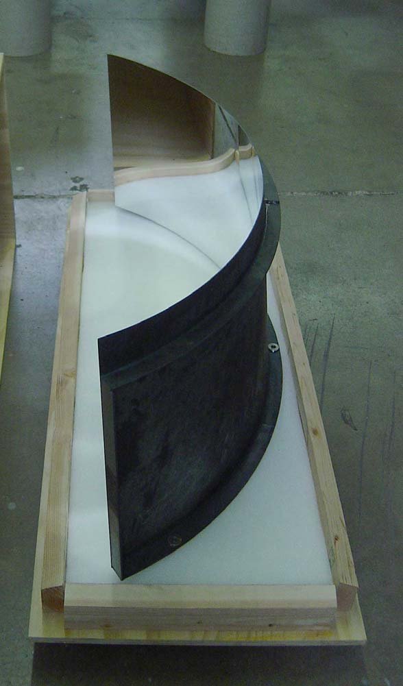
Figure 5. Prototype RICH Mirror, EM readied for shipment to Milan, IT. The EM is shown with aluminum coating and ribs and flange structure to help maintain figure during testing and evaluation by CGS.
Roughness measurements were made and the results show the rms roughness meets the requirement of less than 10nm rms for every point measured. 50 points were measured in an X-Y grid pattern on the EM and typical values did not exceed 8nm rms for any point measured. Slope error measurements were also made with the TOPO indicating that the surface slope error at the measurement locations were less than 1.0mrad as required. The EM was delivered to CGS in April 2004 and the final Flight Model, FM, phase began shortly thereafter.
3. FLIGHT MODEL RICH MIRROR
Based on the results of the EM effort, a process and manufacturing plan was mutually agreed to by CMA and CGS. The process plan involved very specific, detailed, procedural steps to minimize risk in meeting the performance requirements, while maintaining a firm delivery schedule.
As planned, the FM was produced by assembling 3 discrete mirrors of 1/3rd the circumference of the whole mirror. The three mirror sections, before assembly, were already processed as mirrored surfaces and as a result, great care had to be exercised to prevent damage to the optical surface. This posed the greatest challenge to the mirror during the assembly phase.
3.1. FM RICH Mirror Specifications
The RICH mirror specifications were defined by CGS and were driven not only by dimensional and optical requirements, but by requirements for life in a Low Earth Orbit, LEO, environment and an extremely low mass budget. The following are a list of the specifications.
Top Diameter: 1.2m
Bottom Diameter : 1.3m
Mirror Height: 462mm
Weight: Lowest Possible
Circularity: 0.1mm
Concentricity: 0.1 mm max
Maximum Slope Error: 1mrad
Further, the mounting was only allowed from 4 M6 mounting points (90o apart) on the bottom flange. No additional mounts for the mirror were allowed, which was challenging from the point of view of meeting vibrational loading resulting from launch on board the STS. CGS had determined through Finite Element Analysis, FEA, that the design of the FM would meet the load conditions
3.2. CFRP RICH Mirror Components
Figure 6 shows the CFRP composite vertical ribs and flange components. These components were cut using a CNC mill to a high degree of accuracy in their radius. The inner radius of each mirror had to be machined to the outer surface radius of the mirror segments so that when they were attached to the back of the mirror segments they form a circular arc of the exact radius of the mirror. Bearing in mind the tight circularity and concentricity requirements of the conical shape, the radius of the mirror and each component must be perfectly machined and placed during the final assembly. This required that an assembly fixture be produced to hold each component into place during assembly. Figure 7 shows two mirror sections placed in the assembly fixture.
The flange sections were cut in 1/12th arc lengths, 24 sections total. The attachment scheme involved placing 12 sections around the top and bottom edges of the mirror and then laying another layer of 12 sections in an overlapping configuration forming final top and bottom flanges that were two layers thick. The reason for dividing the circumference into arc sections was to allow the assembly fixture define the circularity of the conical shape and not have a continuous ring flange define the circularity as there may be errors associated with the machining. Also, the sectioned flange allowed the ply-orientation of each arc section to be uniformly distributed around the mirror, creating a more quasi-isotropic flange.
The vertical ribs were produced in the form of “L”-shaped brackets, producing a high degree of stiffness along the vertical edges of the separate mirror sections, where each “L” bracket was placed. The placement of ribs and arc sections will be shown in the Assembly section.

Figure 6. Image shows the CFRP flange arc sections and the vertical “L” brackets

Figure 7. Photo shows two mirror sections placed into grooves, which were accurately machined on the top and bottom aluminum plates of the fixture.
4. FM ASSEMBLY
The assembly fixture was designed to carefully place each mirror section for attachment of the vertical ribs and flange sections. The central tube acts as a pilot shaft to guarantee concentricity and circularity of the top and bottom edges of the FM and ensure that the conical axis was vertical.
The mirrors were placed into the groves and the vertical “L” brackets were attached to the edges of each mirror side edge, there were 6 total. The “L” brackets were attached using 1210 A/B adhesive as shown in figure 8.

Figure 8. “L” brackets being glued onto the ends of each mirror.
Another purpose of the “L” brackets was to finally join each mirror to the radial portion of the “L” brackets during final assembly. Once the brackets were in place, the mirror was ready for final assembly.
While placed into the bottom groove plate, all 3 mirror sections were glued while the optical alignments were made at each intersection line between the three mirror sections. This was done visually. It was important to have a smooth and consistent image as a reflected image moves visually from one mirror section to another. Also required was that the image moves from top to bottom between the mirrors as well. Once this operation was complete and the three sections were glued with 1210 A/B, both top and bottom flanges were assembled, again using 1210 A/B Adhesive.
The lower flange sections were simply placed end-to-end around the base of the mirror, which actually sat below the flange by the thickness of the stainless steel mounting insert so that when assembled the mirror sat on the inserts with the very bottom edge of the mirror sat roughly 0.25mm from the floor. The upper flange was assembled with vertical spacers between the floor and the bottom of the flange sections so they could be accurately spaced to the height that corresponded to their inner radius. The first set of upper flange sections were glued at their horizontal mid points to the top surfaces of the “L” brackets. After the adhesive was set, the adjacent flange sections were placed end-to-end to the already attached sections. Once the first complete layer of the upper flange was set into place, small 30mm lap sections were placed to form a lap joint between any 2 sections. So the upper flange was a singlelayer ring with lap joints each flange section end.
Once this operation was completed, the entire mirror was a technically assembled and a cleaning process was performed, the excess glue was ground away and the entire mirror was cleaned and readied for inspection. Figure X9below is a photo of the completed FM ready for shipment.

Figure 9. Image of the FM on the container mount, shown are the upper and lower flanges and vertical ribs in place.
Figure 10 shows the FM after coating with Aluminum + SiO2 at ZOAT in Italy. The mirror is undergoing tests and integration into the rest of the payload for AMS-02.

Figure 10. FM (upside down) after Aluminum +SiO over coating at ZOAT, IT. The mirror was coated on the outside surface as well for environmental resistance.
5. CONCLUSIONS
The RICH mirror program was a combination of a development program and straight procurement. The process development to produce the mirror surface was extensive, involving many obstacles along the way. The mirror, however, was successfully completed, meeting all of the dimensional and optical requirements set by CGS. The mirror was measured using the CMM Facility at The University of Arizona Instrument Shop. CMM measurements verified the dimensional requirements for the mirror were met successfully. The total mirror weight is 8kg. The mirror is undergoing tests and integration into the rest of the AMS-02 experiment.
ACKNOWLEDGEMENTS
The Authors wish to thank Robert Kingsley at the University of Arizona Instrument Shop for his help assistance in the CMM measurement of the FM.