Design of a space-based infrared imaging interferometer
Michael Hart,a,* Douglas Hope,a and Robert Romeob
aHart Scientific Consulting International LLC, Tucson, Arizona, United States
bComposite Mirror Applications, Tucson, Arizona, United States
Abstract
Present space-based optical imaging sensors are expensive. Launch costs are dictated by weight and size, and system design must take into account the low fault tolerance of a system that cannot be readily accessed once deployed. We describe the design and first prototype of the space-based infrared imaging inter- ferometer (SIRII) that aims to mitigate several aspects of the cost challenge. SIRII is a six-element Fizeau inter- ferometer intended to operate in the short-wave and midwave IR spectral regions over a 6 × 6 mrad field of view. The volume is smaller by a factor of three than a filled-aperture telescope with equivalent resolving power. The structure and primary optics are fabricated from light-weight space-qualified carbon fiber reinforced polymer; they are easy to replicate and inexpensive. The design is intended to permit one-time alignment during assembly, with no need for further adjustment once on orbit. A three-element prototype of the SIRII imager has been constructed with a unit telescope primary mirror diameter of 165 mm and edge-to-edge baseline of 540 mm. The optics, structure, and interferometric signal processing principles draw on experience developed in ground-based astronomical applications designed to yield the highest sensitivity and resolution with cost- effective optical solutions. The initial motivation for the development of SIRII was the long-term collection of technical intelligence from geosynchronous orbit, but the scalable nature of the design will likely make it suitable for a range of IR imaging scenarios. © 2017 Society of Photo-Optical Instrumentation Engineers (SPIE) [DOI: 10.1117/1.OE.56.7.071510]
Keywords: infrared imaging; interferometer; surveillance; Earth science.
Paper 170146SSP received Jan. 31, 2017; accepted for publication Jun. 1, 2017; published online Jun. 22, 2017.
1 Introduction
Space-based remote sensing and surveillance have become essential tools for a very broad range of applications, both military and civilian. Weather forecasting has taken advantage of satellite data for over half a century and now relies heavily on data from orbit.1,2 An enormous range of other activities, such as crop monitoring,3–5 emergency preparedness,6,7 the study of climate change,8,9 archaeology,10 urban planning, and many others, all benefit from Earth-imaging systems in space. As the range of space-based sensing capabilities expands, along with the utility of the data they generate, the demand grows to deploy those capabilities more rapidly and at lower cost. There is therefore strong incentive to explore innovative designs, materials, and fabrication techniques that can keep pace with rising operational expectations. This is generally true at all wavelengths, and particularly so in the short-wave (SWIR) and midwave IR (MWIR) bands because of their extended utility at night and under adverse weather conditions on the ground.
Satellite platforms for Earth remote-sensing applications are subject to strict constraints on the size, weight, and power (SWAP) of payloads that may be carried. Furthermore, placing a satellite on orbit is likely to remain expensive, with the cost directly related to the weight of the payload. Minimizing the SWAP parameters is therefore an important driver for any flown sensors. On the other hand, the performance of on- orbit imaging sensors is improved by pushing in the opposite direction, particularly with respect to size. The sensitivity, fundamental resolving power, and achievable contrast of an imager (or indeed any other optical instrument) are all increased with larger collecting aperture. Current satellite
systems for civilian use compromise with telescopes that are by modern ground-based standards very small, generally in the 20 to 50 cm range. The Operational Land Imager (OLI) is typical of a high-performance optical sensor now on orbit.11 The OLI is one of the two primary sensors on board Landsat 8, the latest in a line of Earth-observing sat- ellites stretching back to 1972. It deploys a four-mirror off- axis anastigmatic telescope with the largest mirror dimension being ∼70 cm although the area of the entrance aperture is only 143 cm2. The mirrors themselves are made of Zerodur and they are supported in a graphite truss.12 Despite its small aperture, the entire OLI is massive: including the electronics, the instrument weighs 432 kg.13
The Landsat missions are deployed in sun-synchronous low-Earth orbits (LEO). By contrast, the Geostationary Operational Environmental Satellites (GOES), operated pri- marily as weather observation platforms by NOAA, are in the more hostile geosynchronous environment that is also two to three times more costly to reach per kilogram of pay- load. The primary instrument for the current generation of satellites, GOES-13/14/15, is a visible and infrared imager. The telescope for the instrument has a primary mirror of just 31 cm diameter.14 The newly deployed GOES-16 (formerly GOES-R) satellite has a similar type of instrument, the advanced baseline imager with higher spatial resolution on the ground and faster scan rate, and with a 55-cm-diameter mirror (NOAA recommendations for changes to public notice 8329, amendment to the international traffic in arms regulations: revision of U.S. munitions list category XV and definition of “defense service”, 3 July 2013). We note that in these particular cases, the optics are sized to satisfy sensitiv- ity and field of view (FOV) requirements rather than the demands of spatial resolution. In fact, the resolution of the Landsat 8 and GOES instruments is limited not by any fundamental physical effect such as diffraction at the optical entrance pupil but by the size of the pixels of the focal plane array.
*Address all correspondence to: Michael Hart, E-mail: michael@hartsci.com 0091-3286/2017/$25.00 © 2017 SPIE
The significant role of the collecting optics in determining the capabilities of an instrument in space motivated us to explore how both a large collecting area and high-resolving power might be preserved while at the same time maintain- ing low SWAP values. That goal has led us to adopt a set of design principles, set out below, that have been expressed in a prototype of the space-based infrared imaging interferom- eter (SIRII) described in this paper.
2 Design Principles
Our approach addresses reductions in size, weight, and cost in two distinct ways. First, SIRII is designed as an imaging interferometer. In general, interferometry is a technique that enables a compact high-resolution sensor to be constructed through aperture synthesis: coherent beam combination from substantially smaller optical elements then would be required of a single filled aperture of equivalent resolving power.15,16 Second, to the greatest extent possible, we take advantage
of composite materials in the construction of the sensor. In this way, we seek to keep the overall weight low while retain- ing high stiffness. Both the structure and the primary mirrors of SIRII are fabricated from space-qualified carbon fiber reinforced polymer (CFRP).17 This avoids the mismatches in the coefficient of thermal expansion (CTE) between the optics and their support structure that are typical of the opti- cal systems fabricated from traditional materials, and that lead to significant systems engineering challenges. Further- more, since CFRP structures can be readily replicated, the manufacturing time and per-unit cost, after nonrecurring expenses are retired, are both potentially much lower than for traditional systems.
Reducing the size and mass of the collector optics in space-based instruments such as those described above potentially alleviates other systems engineering require- ments. There is an obvious connection to the size and mass of the support structure. In addition, however, we believe that it may be possible to dispense with the large scanning mir- rors typically placed ahead of imaging systems requiring large FOV, on the order of 10 deg or more, including those on the Landsat and GOES satellites. Scanning is necessary because of the challenge imposed by the Lagrange invariant
in designing optical systems with both large aperture and wide field. Instead, if the optical package is made sufficiently small and light, the entire system can be gimbaled, allowing a substantial subsystem to be removed from the design.
3 Overview of the SIRII Sensor
Our intention in developing the prototype of the collector optics was to demonstrate the construction methods and opti- cal quality of the CFRP materials in a design weighing less than 10 kg. The instrument was to be tailored to operate in wavebands between 1.6 and 3.5 μm, with a full FOV of 6 mrad.
The SIRII concept is illustrated by the solid model of the structural design and the corresponding optical model, built in the optical design code Zemax, in Fig. 1. The optics are arranged as a six-element regular hexagon Fizeau interfer- ometer, in which the entrance and exit pupils are related via a homothetic transformation. This preserves the Abbe sine condition,18 in principle yielding a shift invariant point-spread function (PSF) with resolution determined by the largest baselines between the elements. Designed well, the interferometer mimics a filled aperture telescope with a mask placed over the primary mirror having holes that match the apertures of the interferometer. Fizeau interferom- etry with comounted unit telescopes has a long heritage in astronomy, going back to the multiple mirror telescope (MMT), a six-mirror array commissioned in 1979 on Mt. Hopkins, Arizona. Some years later, active piston compensation of atmospheric path-length errors over five of the MMT’s six apertures led to the demonstration of diffraction-limited im- aging from the 6.9-m-diameter array.19 The technique has been developed further at the Large Binocular Telescope (LBT), with the LBT interferometer combining the beams from its two 8.4-m-diameter primary mirrors.20
The MMT and LBT instruments notwithstanding, ground- based astronomical interferometers typically use widely spaced elements that do not fill the space of all the possible baselines. This leads to holes in the Fourier plane coverage of observed scenes and imperfect imaging as a result. The Center for High Angular Resolution Astronomy 21 array on Mt. Wilson, California, the very large array radio inter- ferometer near Socorro, New Mexico, and the Navy Precision Optical Interferometer (NPOI)22 near Flagstaff, Arizona, are examples of this classic approach. An imaging interferometer, by contrast, deploys its unit telescopes in a geometric arrangement that ensures every possible baseline out to the maximum edge-to-edge separation is sampled.

Fig. 1 (a) The SIRII sensor concept in a solid model showing the CFRP components and (b) as a Zemax model showing the optical components.
In this way, an image may be recovered that, barring signal-to- noise considerations, has the same quality as would be seen from a filled aperture of the same size. In the case of SIRII, the ratio of the unit telescope diameter to the center-to-center spacing is such that all spatial frequencies are sampled: that is, the modulation transfer function (MTF) has no zeros.
As shown in Fig. 2, the SIRII aperture forms a PSF that has an underlying sixfold symmetry but approaches the PSF made by a circular aperture with diameter equal to the circumscribing circle of the interferometer. Figure 2 also shows the azimuthally averaged MTF in each case, normal- ized to the same irradiance. The reduced value of the SIRII MTF at zero frequency reflects the lower overall collect- ing area.
Details of the light paths in the collector optics are shown in Fig. 3. The six unit telescopes each have a primary mirror 165 mm in diameter. The arrangement offers a 540-mm edge-to-edge optical baseline in a package that is substantially smaller than a filled aperture telescope. The primary mirrors have a fast focal ratio of f∕1.06. Scaling one to 540 mm diameter would yield a telescope ∼490 mm long, occupying more than three times the volume of the SIRII collector optics. Furthermore, the Fizeau configuration does not scale in depth as it scales in overall aperture size. Thus, variations on the SIRII sensor can scale in resolution (aper- ture size) while remaining compact.
Of critical concern to the functioning of an optical interferometer is the control of optical path difference (OPD) between the unit telescopes.

Fig. 2 (a) SIRII and (b) single-aperture geometry with equivalent diffraction-limited resolution. The pan- els, left to right, show the pupil geometry, the PSF on a square root scale, and the azimuthally averaged MTF. The SIRII MTF is normalized to the same flux as the single aperture.

Fig. 3 Layout of collector optics and detail of central beam combiner.
High contrast imaging is only achieved if the OPD is less than the coherence length lc of the filter ahead of the focal plane array
lc ¼ λ2∕2πΔλ;
where λ and Δλ are the center wavelength and bandwidth of the filter, respectively. SIRII is intended to operate in the astronomical HKL windows between 1.6 and 3.5 μm, with the widest bandwidths consistent with good atmospheric transmission in order to assure the highest signal- to-noise ratio. Filters designed to match these three windows have coherence lengths between 1.5 and 4 μm. Independent of any other alignment tolerances, OPD errors must therefore be maintained below about 1 μm.
Maintaining the OPD to within this tolerance guarantees high contrast in the fringes developed by each pair of unit telescopes. By itself, though, it does not guarantee imaging with high Strehl ratio. To achieve that, the pathlength errors must be held to an integer number of waves to within a frac- tion of a radian of phase, or about 100 nm at the shortest wavelength of operation. While our initial alignment, dis- cussed in Sec. 6, will achieve that, we do not expect the path- lengths to hold to this tolerance indefinitely while SIRII is on orbit.

Fig. 4 Design of the SIRII collector unit telescopes.
Instead, we rely on an image restoration algorithm, as described in Sec. 7, to offset the effects of larger phase errors.
3.1 Optical Design: Collector
The optical design is conceptually divided into two subsys- tems, separated by the central plane of the CFRP optical bench that provides the core stiffness of the structure. The collector optics are attached to the front of the bench, and the imager optics to the rear. Light passes into the imager through a hole in the center of the bench. The unit telescopes of the collector are a modified afocal Cassegrain–Mersenne design that offers a very compact format with readily manu- facturable, almost parabolic aspheres for the primary and secondary mirrors M1 and M2. Design details and the layout are shown in Fig. 4. The collector optics as a whole have an angular magnification of 7.0, which leads to manageable beam sizes and excellent performance over the 6-mrad design FOV, as shown by the MTF in Fig. 2. A collimated beam is presented to the imager optics, which see an entrance pupil that appears just behind the unit telescopes’ secondary mirrors.
The optics are sized to prevent vignetting over the full FOV with the exception of the pyramid mirror M4. Given the choice of FOV and the requirement to preserve the beam geometry in order to satisfy the sine condition, there are no remaining degrees of freedom to adjust the size or spacing of the M4 facets. The vignetting is therefore unavoidable. The magnitude of the effect though is modest, quantified in Fig. 5, and does not prevent high-quality im- aging. The main effect is a small reduction (about 5%) in contrast in the PSF at the edge of the FOV (an effect identical to the loss of fringe visibility in a conventional two-beam interferometer when the beam intensities are unequal).
The effective focal lengths of the six unit telescopes must be well matched. If they are not then the image scales will differ, leading to loss of coherence toward the edge of the FOV. An analysis in Zemax shows that if the M1-M2 sep- aration is used as a compensator, and the loss of contrast is held to 10%, the requirement on the difference in radius of curvature between the primary mirrors is 70 μm.

Fig. 5 Vignetting for the collector optics out to a radius of 3 mrad.
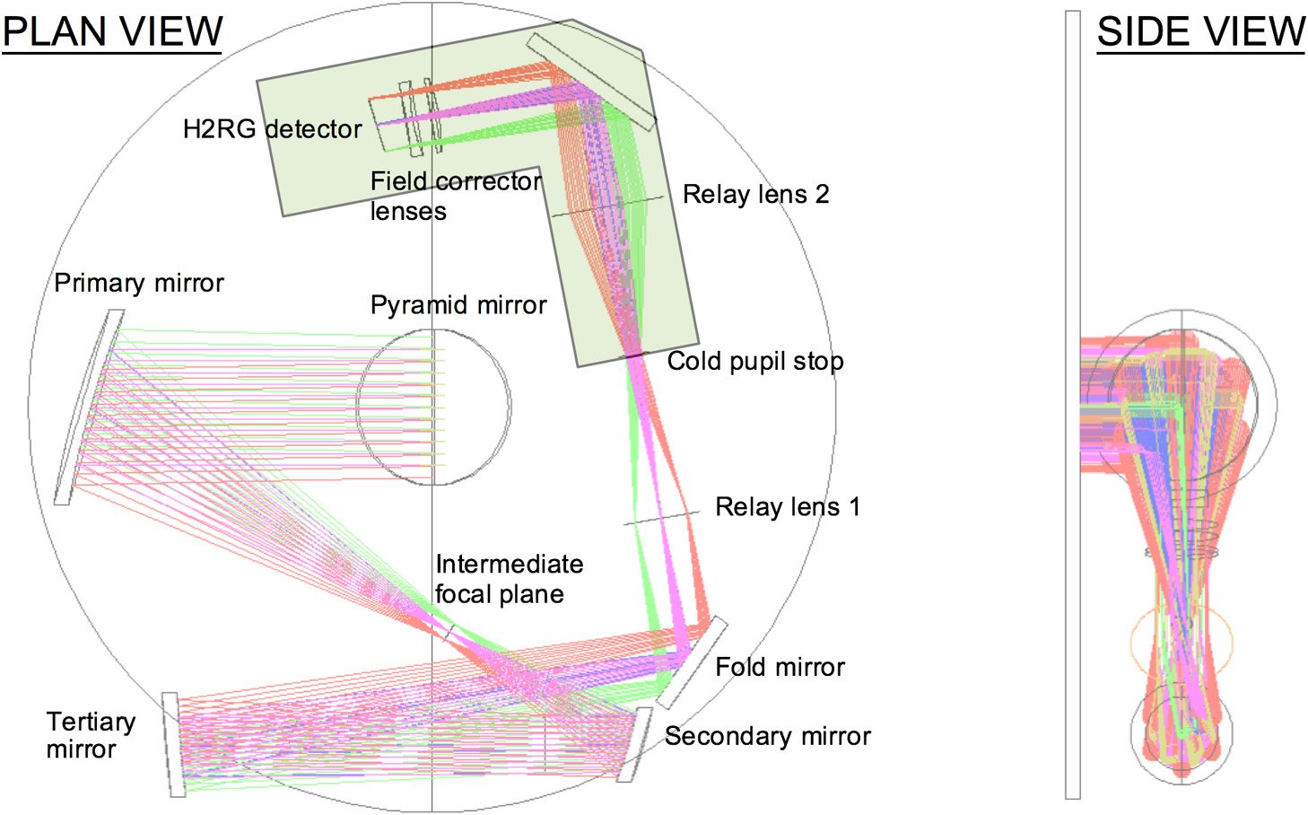
Fig. 6 Layout of the SIRII imaging optics.
This is well within reach of the standard replication techniques for CFRP optics. An identical requirement applies to the secondary mirrors. In this way, good stigmatic imaging is maintained over the full FOV.
3.2 Optical Design: Imager
Although not part of the prototype construction, the imaging optics mount to the lower side of the optical bench. The chal- lenge is to accommodate the 6-mrad FOV with diffraction- limited image quality while restricting the optics to a small volume. This is not easy because of the Lagrange invariant which declares that ray angles grow larger as the size of the optical beam is reduced. The layout is shown in Fig. 6, where the large circle on the left is an approximate representation of the 560 mm size of the hexagonal optical bench. The shaded region shows the outline of the cryostat necessary to house the IR focal plane array. Figure 7 shows the Strehl ratio achieved by the design over the FOV as modeled in Zemax at the conservatively short wavelength of 1.0 μm.

Fig. 7 Modeled Strehl ratio of SIRII across its 6 mrad FOV, computed at 1 μm wavelength.
The off-axis design of the relay leads to a modest degree of asymmetry in the Strehl ratio with respect to the center of the FOV.
Note that although the performance of this design is excellent over the FOV and the full range of wavelengths, it requires custom aspheric mirrors for the primary, secon- dary, and tertiary. We have yet to demonstrate fabrication of these components in CFRP, but our experience with the primary mirrors of the collector optics, discussed below, leads us to be optimistic that the same process will be suc- cessful in making the imager mirrors.
3.3 Considerations for Spacecraft Integration
The FOV of SIRII is inadequate to make it an effective remote sensing instrument without the ability to scan. As we have noted, our goal is to avoid the requirement for a separate scanning mirror. Assuming a 45-deg angle of inci- dence, such a mirror would have to be essentially elliptical with minimum dimensions of 54 × 77 cm. A conventional mirror of that size in Zerodur, aggressively lightweighted by 70%, could be expected to weigh ∼25 kg, more than SIRII itself. Therefore, we believe that a more natural approach is to mount the entire SIRII assembly in a two-axis gimbal attached directly to the spacecraft host. Mounting points for the gimbal would attach at two locations on opposite sides of the central optical bench, taking advantage of the natural torque balancing between the collector optics on the front side and the imager optics on the back.
Figure 8 presents the overall systems architecture of the SIRII sensor as it would be packaged for integration into a host platform. The package includes the SIRII optical assembly itself, together with the focal plane array and con- trol, cryocooling for the detector, as well as thermal control of the sensor as a whole, and payload control electronics.
CFRP Material
All of the structural components of SIRII as well as the pri- mary mirrors of the collector optics are constructed from the same CFRP material: high modulus, pan-based carbon fibers
Fig. 8 Systems schematic of the SIRII sensor packaged for flight.
impregnated with a cyanate ester resin system. CFRP has long been used to manufacture stiff, lightweight structures. Its use in the fabrication of mirrors stretches back about two decades, with research continuing to improve the optical quality for terrestrial and space applications.23–25 Details of the fabrication techniques used to manufacture the SIRII prototype components are given in Ref. 26.
The design of the sensor requires an understanding of the material’s CTE and stiffness, since these properties relate to performance on orbit. To mitigate the effects of temperature changes, we wish to tailor the CTE to be as low as possible in the direction parallel to the optical axis, which is achieved by appropriate orientation of the carbon fibers. In the radial direction, SIRII is much more tolerant of thermal expansion. In this space, the six unit telescope beams are collimated. Isotropic in-plane thermal expansion or contraction will therefore not affect image quality, though since the distance to the entrance pupil will change as seen by the focal plane array, the image scale will change slightly.
Low CTE in a preferred direction is achieved by orienting
the carbon fibers along the axis of interest. The fibers them- selves have negative CTE, which is balanced by the positive CTE of the resin to produce a net effect close to zero. Unidirectional lay-ups produce laminate properties that are biased in the fiber direction and assume the fiber mechanical and thermal properties. On the other hand, quasi-isotropic lay-up orientations produce more in-plane uniformity. Both arrangements are used in the SIRII prototype. For example, the optical bench is built up as a 40-mm-thick honeycomb
sandwich structure with the front and back plates using a lay-up with sixfold rotational symmetry. Both geometries reflect the symmetry of the optics and ensure that in-plane thermal effects are as uniform as possible. The primary mir- rors are built up in a similar way. By contrast, the vertical pylons holding the secondary mirror structure above the opti- cal bench use a unidirectional lay-up along their length.
Thermal Analysis
A static thermal analysis of the telescope structure and optics has been carried out. The analysis starts with a thermal study to yield an equilibrium temperature distribution of the entire structure under expected thermal load conditions. Finite element modeling then yields the stress and displacements resulting from the temperature distribution, assuming an ini- tial stress-free temperature of 22°C. We analyzed the SIRII assembly under expected thermal load cases for two space- borne applications with stations at LEO, appropriate for earth-observing satellites, and geosynchronous earth orbit (GEO) appropriate for communications and weather satel- lites. These are shown in Fig. 9; the GEO thermal loading model assumes an additional worst case load where the sun is shining on a part of the front telescope structure, where it is incompletely shielded.
For purposes of the thermal analysis, the structure is assumed to be mounted to the satellite bus by three brackets at the edge of the breadboard. The structural elements are black on the surfaces exposed to the optics to suppress glints,
Fig. 9 Load cases for the SIRII thermal study. (a) LEO, with front loading from the earth and solar loading from the side. (b) GEO that includes direct solar illumination on one side of the optical structure.
particularly from direct solar illumination. The structure is assumed to have a reflective coating on the outside edges that are not exposed to the optics to reduce the radiative cou- pling to the surroundings.
The thermal loading on the telescope assumes:
The temperature of the satellite bus is held at 15°C where it connects firmly to the optical telescope assembly (OTA) mounting pads and brackets.
The telescope structure is surrounded by a tubular solar shield that includes 10 layers of thermal multilayer insulation (MLI). The structure then sees radiative loading from the temperature of the shield with an effectively reduced OTA outer emissivity due to the MLI. The “inside” zone of the structure and the optics see radiative loading at the surface temperature of the earth. A worst case daytime load is assumed.
LEO Thermal Load Case
The LEO thermal load case, shown in Fig. 10, assumes the sensor is looking at the daylit earth, with only a
perpendicular incidence of sunlight on the MLI; no CFRP components are exposed to direct sunlight. The equilibrium thermal distribution has a mean temperature of 14.7°C with a maximum front-to-back gradient of 0.6°C. At equilibrium, the analysis shows that the maximum displacement is
2.8 μm. The primary displacement is a change in separation of the M1 and M2 mirrors: this is benign and may readily be corrected by adjusting the focus of the camera. The thermal distribution of the telescope structure and optics are pri- marily determined by the temperature of the satellite bus connection. The radiative loading from the earth and earth’s atmosphere has only a small influence on the temperature distribution of the system.
GEO Thermal Load Case
This load case assumes a telescope look angle close to the limb of the earth near sunrise or sunset, resulting in direct sunlight exposure on the top-left side of the secondary sup- port structure as shown in Fig. 9. We adopt this as the worst- case thermal load for sensor operation. It is of particular con- cern because it will result in transverse temperature gradients that are much less easily dealt with than the largely axial
Fig. 10 (a) Temperature distribution and (b) thermally induced displacements for thermal equilibrium in the LEO load case.
Fig. 11 (a) Temperature distribution and (b) thermally induced displacements for thermal equilibrium in the GEO load case.
gradients seen in the LEO case. Any transverse alignment errors introduced by thermal gradients must be within the optical tolerances of the design.
The equilibrium temperature distribution, shown in Fig. 11, for the GEO case where direct sunlight illuminates the secondary support structure has considerably higher thermal gradients than for the LEO case. Temperature differ- entials of 83°C are seen. Nevertheless, the induced displace- ments, also shown in Fig. 11, are acceptable. The worst displacement is decentration of the exposed secondary mir- rors with respect to their primary mirrors by about 14 μm. This is well within the 85 μm tolerance of the design. Furthermore, no other alignment tolerance is in danger of being exceeded.
Prototype Development
As a means to test the fabrication technologies needed to build and integrate the CFRP optics and structure, we have constructed a full-scale prototype of the SIRII collector optics. Because of cost constraints, only three of the six unit telescopes were made. All the structural components were fabricated in CFRP as well as the three unit telescope pri- mary mirrors, using a proprietary replication process from a convex aspheric glass mandrel. One of the three primary mirrors is shown in Fig. 12 after coating. The optical surface is supported by a light-weight rigid CFRP honeycomb struc- ture. An example interferogram and surface map are shown in Fig. 13. During the release of a test mirror early in the
Fig. 12 One of the three CFRP primary mirrors, 165 mm in diameter, fabricated for the SIRII prototype.
development, the inner edge of the mandrel was unfortu- nately chipped, leading to an area of unsatisfactory surface quality in the final mirrors that is masked out in Fig. 13. The figure error over the remaining area is 34 nm rms with most of the error in relatively low-order aberration with the excep- tion of a downturned edge. The other two primary mirrors showed figure error of 31 and 38 nm rms. This is acceptable for operation in the SWIR and MWIR bands.
The complete prototype is shown in Fig. 14. The convex aspheric secondary mirrors, and the flat M3 and M4 peri- scope mirror facets are fabricated from glass. Since they are small, ∼20 to 30 mm in size, they contribute little to the overall weight.
The goal of the prototype is to understand how to build a flight unit in such a way that no actuated degrees of freedom are required in the collector. Once the unit is assembled, all the parts are to be locked in place. This approach reduces weight and power requirements and altogether avoids the issue of a dead actuator leading to mission failure. Achieving the necessary accuracy in optical fabrication and alignment is challenging: tight tolerances are required on the magnification of the six unit telescopes as well as the overlap of their focal planes. Furthermore, the optical path lengths through the telescopes must be equal, and the pupil geometry must be preserved at the focal plane. Positional and angular tolerances for the optical components are generally on the order of 50 μm and 0.05 deg, respec- tively, and the M1 and M2 radii of curvature must be matched to within 200 μm. In this respect, the replication process for the primary mirrors is ideal: all three have mea- sured radii within 3 μm of the glass mandrel. The convex secondary mirrors, individually fabricated, are also well matched, within 15 μm. The one particularly tight criterion is the 1 μm OPD match between the telescopes.
Meeting these alignment tolerances requires fine position
control and optical feedback as the components are assembled. In the prototype, the required degrees of freedom are implemented through tip-tilt adjustment of the M3 mir- rors, and tip-tilt-piston of the M4 facets using picomotors. In addition, manual adjustment of the M1-M2 separation and coalignment is implemented to control unit telescope colli- mation. Collectively, these degrees of freedom allow position control of the unit telescopes’ focal planes and pupil planes as well as pathlength adjustment. The motors are built in to create an integrated unit but are designed to be removed after
Fig. 13 Masked interferogram and surface map of one of the three primary mirrors.
Fig. 14 The SIRII prototype with three of the six unit telescopes populated.
Table 1 SIRII component masses.
Component
Mass/unit (g)
No. of units
Total mass (g)
Bench
1205
1
1205
Top end pylons
54
6
324
Top end structure
584
1
584
Mount L-brackets
19
3
57
M1
229
6
1374
M2 and mount
10
6
60
M3 and mount
61
6
366
M4
30
6
180
M4 support
239
1
239
Total weight
4389
final alignment. Production models, however, would see the same controls implemented in external jigging. To date, opti- cal tests have been limited by fabrication errors on the sec- ondary mirrors, manufactured by a third-party vendor, which degrade the unit telescope image quality. If those can be replaced, double-path optical tests of the prototype with a full-aperture retroreflector are planned that will establish the as-built tolerances of the structure and the actual align- ment and final assembly procedures.
As built with three unit telescopes, the prototype collector assembly weighs 3.4 kg, excluding the picomotors. A break- out by subassembly is shown in Table 1. Each unit telescope contributes approximately an additional 330 g of hardware, so a fully populated version of SIRII would weigh 4.4 kg. For comparison, the CDK20, a commercial 0.51 m telescope optical tube assembly with a carbon fiber truss (PlaneWave Instruments, Rancho Dominguez, California), weighs 64 kg without the mount or instrumentation.
Numerical PSF Restoration
To obtain the highest image quality from the sensor’s cam- era, the optical PSF may be deconvolved numerically from imagery post facto. Over the sensor’s operational lifespan on orbit, some creep of the structure is inevitable from long- term outgassing of the material and exposure to radiation. These small movements will result in changes to the PSF. This presents a twofold challenge: first to characterize the PSF and then effectively deconvolve it from the data. We further expect that the PSF will not be shift-invariant since some possible motions of the optical components will lead to field-dependent pathlength errors.
The processing algorithm relies on a parameterization of the PSF, which is characterized by 25 variables correspond- ing to alignment errors within and between the six unit tele- scopes. These are relative image shift (2), focus, scale, and path length for each telescope, with absolute values not being of concern. (It is of course necessary to control absolute focus, but that will be done by adjusting relay lens 2 inside the cryostat.) The values of these parameters are expected to change only slowly over time but must be periodically recomputed from reference images. Ideally, these images
Fig. 15 (a) Pristine ground scene, (b) simulated SIRII image with perfect PSF and added noise, (c) simu- lated image with piston errors between segments, and (d) after image restoration.
would be of star fields, but our estimation algorithm can operate with extended scenes, subject to some degradation of performance that depends on the spatial frequency content of the scene. It is a variant of the daylight object restoration algorithm (DORA) presently used to recover high-quality images of artificial satellites from ground- based telescopes.27 DORA is a nonlinear multiframe algo- rithm that enforces both non-negativity and bandwidth constraints on the restored image.
Computing the PSF model is computationally intensive. The model will therefore best be computed at a ground- station from reference images downlinked at a slow rate, interleaved with the normal sensor data and telemetry. As an example, the effects on image quality of alignment error is demonstrated in Fig. 15. The original pristine scene, Fig. 15(a), is a section 34 km wide cropped from a Landsat 2 multispectral scanner image of a region of farm- land in eastern Oregon centered at about 44.1° N 117.4° W. The native ground sample distance is 68 m. This matches well the angular subtense that would be chosen for the pixels of a diffraction-limited MWIR camera on SIRII with the instrument at GEO: at 3 μm wavelength, the beam footprint on the ground would be 200 m. For the simulation, the image is convolved with the SIRII PSF, and shot noise is added to simulate an exposure of 0.1 s, yielding a mean irradiance per pixel corresponding to 3 × 10⁵ photons. Figures 15(b) and 15(c) show the results with an unaberrated PSF and an exam- ple with path length errors introduced between the unit telescopes. This has the effect of diluting the energy in the PSF among several speckles, which leads to image blur. Figure 15(d) shows the aberrated image after restoration. To avoid unacceptable noise amplification in the high spatial frequencies, the restoration uses Tikhonov regularization
Fig. 16 Azimuthally averaged MTFs of the aberrated and restored images in Fig. 15.
based on the estimated noise-to-signal ratio in the image at the spatial frequencies of concern. The azimuthally aver- aged MTFs for the aberrated and restored images are shown in Fig. 16. The aberration results in a significant decrease in the MTF at all spatial frequencies.
We anticipate that the calibration will be necessary only infrequently. The Hubble Space Telescope (HST) provides a point of reference: over a 20-year period, the spacing between the primary and secondary mirrors has shrunk by ∼150 μm, or 0.003%, an effect attributable to the contin- ued creep of the graphite-epoxy truss holding the two mirrors.28 The initial, fastest, shrink rate was ∼75 μm∕year, or 1.5 × 10⁻⁵ per year. While the HST material is not identical to the CFRP used in SIRII, the anticipated behavior caused by
outgassing from the epoxy matrix is expected to be similar. Given the characteristic dimensions of the SIRII structure, we should expect initial movement on the order of 2 to 4 μm∕year. Motions large enough to require recalibration of the PSF are therefore not anticipated on time scales shorter than months.
Conclusions
The SIRII design demonstrates the feasibility of a robust, light-weight optical system that offers the resolving power of a filled-aperture telescope in a package one-third of the volume and an order of magnitude less weight. The quality of the CFRP optics is satisfactory for operation in the SWIR and MWIR bands, although more work is required to reduce figure errors to the point where high-quality imaging could be expected at visible wavelengths. The thermal behavior of the CFRP material and the fact that the primary optics and the supporting infrastructure are fabricated from the same material make the design robust to temperature gradients that would be detrimental to traditional metal and glass opti- cal systems.
A key aspect of the design philosophy is to assemble the sensor as a rigid unit that, once fully integrated, cannot be misaligned by thermal or mechanical disturbances in the nor- mal operating environment. This requires careful attention to the assembly process, during which optical feedback is needed to assure that the components are precisely posi- tioned. This is an aspect of SIRII that has yet to be demon- strated; ongoing work is planned that will rely on the micropositioning actuators built into the prototype to estab- lish the detailed alignment and final assembly procedures.
While the primary inspiration for SIRII is to provide tech- nical intelligence from platforms at GEO, the design concept is readily adaptable to a range of other applications where
light-weight, compact IR optics are of potential value. These will generally be missions flown on spacecraft, where launch cost is a primary consideration, and on unmanned aircraft where weight and power capacity are limited. Examples include early detection of forest fires that may present a threat to population centers, and water management and crop differentiation to support commercial agriculture busi- nesses. This is likely to be of particular value in regions such as California and the Arabian peninsula that provide food for residents of wide geographic areas and, yet, are subject to severe water shortages.
Finally, the methods and techniques that underlie SIRII can be extended to the development of a new class of sensor. The ready availability of tooling to produce replicated optics and completed CFRP assemblies means that customized sen- sors on the SIRII model can be produced to order with rapid turn-around, on the order of a month, without requiring a large inventory of costly components.
Acknowledgments
This work has been supported by the US Air Force Research Laboratory under contracts FA8650-13-M-1634 and FA8650-14-C-1800.
References
J. T. Houghton, “Importance of satellites for weather forecasting,”
Nature 326, 450–450 (1987).
H. R. Hertzfeld, R. A. Williamson, and A. Sen, “Weather satellites and the economic value of forecasts: evidence from the electric power indus- try,” Acta Astronaut. 55, 791–802 (2004).
L. Guanter et al., “Global and time-resolved monitoring of crop photo- synthesis with chlorophyll fluorescence,” Proc. Natl. Acad. Sci. U. S. A. 111, E1327 (2014).
K. Y. Guan et al., “Photosynthetic seasonality of global tropical forests constrained by hydroclimate,” Nat. Geosci. 8, 284–289 (2015).
B. F. Wu et al., “Global crop monitoring: a satellite-based hierarchical approach,” Remote Sens. 7, 3907–3933 (2015).
G. Denis et al., “The evolution of Earth observation satellites in Europe and its impact on the performance of emergency response services,” Acta Astronaut. 127, 619–633 (2016).
S. Voigt et al., “Global trends in satellite-based emergency mapping,”
Science 353, 247–252 (2016).
J. R. Norris et al., “Evidence for climate change in the satellite cloud record,” Nature 536, 72–75 (2016).
W. Z. Yang et al., “Satellite climate data records: development, appli- cations, and societal benefits,” Remote Sens. 8, 331 (2016).
R. Lasaponara and N. Masini, Eds., Satellite Remote Sensing: A New Tool for Archaeology, Springer, Berlin (2012).
J. R. Irons, J. L. Dwyer, and J. A. Barsi, “The next landsat satellite: the landsat data continuity mission,” Remote Sens. Environ. 122, 11–21 (2012).
E. J. Knight and G. Kvaran, “Landsat-8 operational land imager design,
characterization and performance,” Remote Sens. 6, 10286 (2014).
NASA, USGS, “LDCM press kit,” February 2013, https://www.nasa. gov/pdf/723395main_LDCMpresskit2013-final.pdf (13 June 2017).
NASA, NOAA, “GOES N data book,” February 2005, https://goes.gsfc.
nasa.gov/text/GOES-N_Databook/databook.pdf (13 June 2017).
A. Labeyrie, S. G. Lipson, and P. Nisenson, An Introduction to Optical Stellar Interferometry, Cambridge University Press, Cambridge (2006).
S. K. Saha, Aperture Synthesis. Methods and Applications to Optical Astronomy, Springer, New York (2011).
R. C. Romeo, R. N. Martin, and K. Bollweg, “Discussions on radiation and space environment exposure of replicated optical mirrors produced from carbon composites,” Proc. SPIE 9616, 961602 (2015).
M. Born and E. Wolf, Principles of Optics, 7th ed., p. 179, Cambridge University Press, Cambridge (1999).
M. Lloyd-Hart et al., “Direct 75 milliarcsecond images from the multi- ple mirror telescope with adaptive optics,” Astrophys. J. Lett. 402, L81– L84 (1993).
P. M. Hinz et al., “Overview of LBTI: a multipurpose facility for high spatial resolution observations,” Proc. SPIE 9907, 990704 (2016).
H. McAllister et al., “CHARA optical/IR interferometric array project,”
Proc. SPIE 2524, 180 (1995).
D. J. Hutter et al., “NPOI: recent progress and future prospects,” Proc. SPIE 7013, 701306 (2008).
Z. Yang et al., “Influence of layup and curing on the surface accuracy in the manufacturing of carbon fiber reinforced polymer (CFRP) composite space mirrors,” Appl. Compos. Mater. 1–12 (2017).
C. Zeng, X. Yu, and P. Guo, “Active deformation and engineering analy- sis of CFRP mirror of various lay-up sequences within quasi-isotropic laminates,” Proc. SPIE 9281, 92810O (2014).
S. Utsunomiya, T. Kamiya, and R. Shimizu, “CFRP composite mirrors for space telescopes and their microdimensional stability,” Proc. SPIE 7739, 77392M (2010).
R. C. Romeo and R. N. Martin, “Progress in 1 m-class, lightweight, CFRP composite mirrors for the ULTRA telescope,” Proc. SPIE 6273, 62730S (2006).
D. A. Hope et al., “Myopic deconvolution from wave front sensing for images acquired with large spectral and temporal bandwidth,” in Proc. AMOS Techology Conf., p. E51 (2013).
M. D. Lallo, “Experience with the Hubble Space Telescope: 20 years of
an archetype,” Opt. Eng. 51, 011011 (2012).
Michael Hart is an associate professor in the College of Optical Sciences at the University of Arizona and the founder of HartSCI. He specializes in the implementation of advanced adaptive optics for large astronomical telescopes and other optical systems, including tomographic wave-front sensing and deformable mirror development. Additional research focuses on the development of physically con- strained image deconvolution and video enhancement algorithms, automatic target recognition, and object-independent wave-front sensing.
Douglas Hope has been active in the field of image postprocessing and information theory for over a decade. He received his PhD in physics from the University of New Mexico in 2004. His research has addressed the problem of image reconstruction from optical inter- ferometer data using statistical information theory and the information- theoretic framework on which the techniques for object estimation rest. He joined the HartSCI team as a senior staff scientist in 2010.
Robert Romeo is the founder and president of Composite Mirror Applications, Inc. He received his BS degree in aerospace engineer- ing from the University of Arizona with an emphasis on materials sci- ence and composites. He has headed the development of some of the largest and most accurate replicated optical surfaces ever made. He has won two NASA Tech Brief Awards for innovative work producing deformable primary mirrors for space telescopes and for large-scale CFRP adaptive optics.