Naval Prototype Optical Interferometer (NPOI) upgrade with lightweighttelescopes and Adaptive Optics: a status update
Sergio R. Restaino1, Jonathan R. Andrews1, Tom Armstrong1, Christopher C. Wilcox1, Robert Romeo3, Robert Martin3
Abstract
The portability of meter-class telescopes has been limited by the weight of the mirror, tube assembly and the mount required to provide pointing and tracking. The novel lightweight carbon fiber reinforced polymer telescopes being developed for array population at the Naval Prototype Optical Interferometer are orders of magnitude lighter than traditional telescopes. When combined with a lightweight carbon fiber mount, these telescopes will be easily transportable from one telescope station to another to change the interferometer baseline. The mount for a lightweight telescope is currently under development at Composite Mirror Applications, Inc. This paper reports on the design constraints of the mount, the scalability to larger aperture telescopes and the integration of sensors to measure the performance characteristics of this system during operation.
Naval Research Laboratory
Remote Sensing Division, Code 7216 3550 Aberdeen Ave SE
Kirtland AFB, NM 87117
New Mexico Institute of Mining and Technology Electrical Engineering Department
801 Leroy Place
Socorro, NM 87801
Composite Mirror Applications 1638 S. Research Loop, Ste 100
Tucson, AZ 85710
Keywords: light weight telescope, telescope mechanics, interferometry.
1. Introduction
The Naval Prototype Optical Interferometer (NPOI) is the world’s only long baseline optical interferometer operating in the visible region, i.e. wavelengths below 0.8 µm. It is also the only optical interferometer capable to recombine up to six beams, from different apertures, simultaneously. A diagram of the current layout of the NPOI is shown in figure 1, where the squares represent existing pads where telescopes can be mounted or moved to, and the circles represent current usable apertures. Currently the NPOI uses Siderostats, i.e. flat mirror that track the object in the sky and redirect its light into the beam relay system. The collection aperture is limited to only 25 cm to avoid atmospheric turbulence problems. Thus the overall sensitivity of the instrument is limited to objects with a visual magnitude of 6.
Restaino, S.R.; Andrews, J.R.; Armstrong, T.; Wilcox, C.C.; Romeo, R.; Martin, R. (2006) Naval Prototype Optical Interferometer (NPOI) Upgrade with Light-Weight Telescopes and Adaptive Optics: A Status Update. In Space Sensing and Situational Awareness (pp. 22-1 – 22-8). Meeting Proceedings RTO-MP-SET-105, Paper 22. Neuilly-sur-Seine, France: RTO. Available from: http://www.rto.nato.int/abstracts.asp.
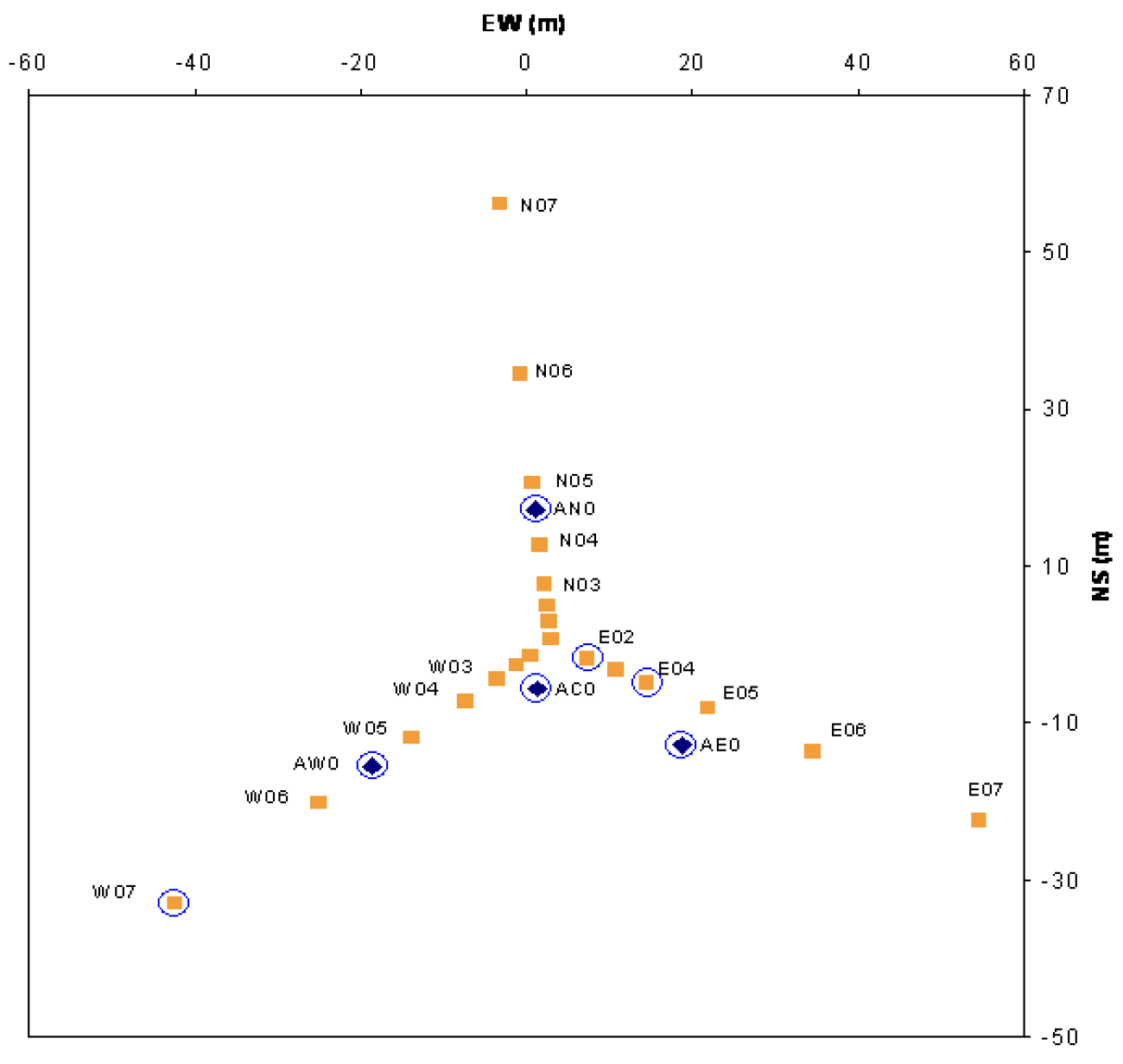
Figure 1: Lay-out of the inner portion of the NPOI interferometer. Squares represent existing pads, the circles are existing apertures mounted on pads. Station separation is labeled on each axes in meters
Recent investigation has aimed at increasing the sensitivity of the interferometer by implementing larger apertures for light collection [1]. When coupled with adaptive optics [2], the NPOI hopes to acquire visual magnitude 12 objects. However, building dozens of meter class telescopes for array population is too costly, and building several telescopes that can be moved from station to station is impractical considering the weight of traditional telescopes. Therefore, the use of Carbon Fiber Reinforced Polymer (CFRP) materials was explored for telescope construction [1]. There are several advantages to using CFRP for telescope construction, including an order of magnitude decrease in weight, allowing easier transportation from station to station on the array. As all components of the telescope, including optics, are constructed from composite materials having a low coefficient of thermal expansion, dimensional changes due to temperature variations can be minimized. Also, since all optics are made from a single high precision tool, duplicate components can be manufactured for much less than traditional steel and glass telescopes [3].
2. Light weight telescope
In order to meet the visual magnitude requirements, 1.4 meter Cassegrain telescopes were designed with very small secondary mirrors being suitable for the narrow field of view requirements at the NPOI. Although CFRP material offers several advantages, including low coefficient of thermal expansion and thermal conductivity, the material and construction methods had to be explored in detail to ensure their suitability for telescope realization. The analysis of the construction materials and methods have been discussed previously [3,4]. Construction of optical quality surfaces from this material required an iterative process to meet the near diffraction limited performance required in the design. Therefore, a 0.4 meter telescope was initially constructed as a prototype. This provided a fully functional telescope available for testing while the 1.4 meter telescope was under development.

Figure 2: Exploded view of 0.4 meter CFRP telescope prototype
The development of the 1.4 meter telescope will require adaptive optics (AO) to correct for the harmful effects of the atmosphere on the resolving power of the interferometer [5]. Traditional AO system have been large add-ons to meter-class telescopes.
Technological advancements in computer control coupled with Micro-Optical-Electro- Mechanical Systems (MOEMS) and MEMS hardware have considerably reduced the size required for an AO system [6].
The requirements for the AO system on 1.4 meter telescope necessitated the development of a 0.4 meter integrated telescope and AO system for prototyping and development.
This design includes the 0.4 meter CFRP telescope and an enclosure and Altitude- Azimuth fork all constructed from CFRP. This system will allow the integration and testing of the AO system into the portable telescope. Exploration of AO systems will include the new combined wavefront corrector described by Wilcox, et al, and Teare, et al [7,8].

Figure 3- Lightweight telescope mounted on portable AO system and lightweight mount.
3. 0.4 meter CFRP telescope and mount with integrated AO
The prototype 0.4 meter CFRP telescope has been under development since 2004. The optical telescope assembly (OTA) including all structural supports and optics weighs roughly 10 Kg. A commercially available 0.4 meter Meade telescope weighs roughly 57 Kg. This lower mass and lower rotational inertia helps reduce the mount mass, and in turn, reduces the drive power requirements for tracking. The 0.4 meter system shown in figure 3 includes the drive motors, an electronics rack constructed from CFRP and aluminum, and a CFRP AO box and breadboard. The total mass of this system is currently 112 Kg, while the integration of the optics and electronics should add less than 30 Kg of mass. The largest contributor to the mass is the aluminum and CFRP electronics rack mounted directly underneath the telescope fork. This system could be reconfigured with the electronics box setup in a fixed location to maintain lower weight of the OTA, mount, drive motors and AO. As a comparison, the 0.4 meter Meade telescope weighs 144 Kg without AO. All mass estimates are outlined in table 1.
Table 1. Mass of 0.4 meter components

The performance of the drive system is dependent on 3 critical components: the drive motors and geometry, the encoders, and the servo electronics. A direct drive system was chosen for maximum stiffness and pointing precision. This drive system is realized with ultrasonic piezoelectric motors manufactured by Nanomotion, Ltd. driving a static ceramic ring. This unique drive configuration is possible because of the low mass (and low rotational inertia) of the system. Using the specifications provided by Nanomotion, the maximum slew speed is expected to exceed 20 deg/s with tracking speed exceeding 1 deg/sec.
The encoders are Renishaw optical encoders with a readout resolution of 0.04 arcseconds. The system accuracy is quoted as about 1 arcsecond which are largely systematic errors which can be compensated for in the mount drive model. The servo is controlled by a commercial control card designed for high accuracy and ease of implementation.

Figure 4- Nanomotion piezo drive motors (left and right), white ceramic drive ring, and quadrature optical encoder head (center) on the altitude axis of 0.4 meter telescope.
4. 1.4 meter CFRP mount
As the 0.4 meter telescope was designed with upscaleability in mind, the design and implementation of the 1.4 meter OTA and CFRP mount is progressing with relative ease. Many possible hangups and slowdowns were discovered during the construction of the 0.4 meter OTA. The design drawing for the 1.4 meter OTA is shown in figure 5 and the current realization of the telescope base is shown in Figure 6.

Figure 5- Computer drawing of 1.4 m concept
The 1.4 meter OTA is currently under development at Composite Mirror Applications with a forecasted weight of 120 Kg including all optics. A traditional steel and glass telescope of comparable size can easily weigh an order of magnitude more. As such, a tradtional mount cannot be used. Using lessons learned from the 0.4 meter mount, the same encoders will be used on both axes, however, piezoelectric drive motors may not be sufficient. A direct drive system will still be implemented, but the largest piezoelectric motors currently available will not have enough power to accurately point the telescope and meet the performance requirements of the drive. As this telescope will populate the array at the NPOI, most tracking will be at sidereal rate. However, the drive system will be over-engineered to slew at around 2 degrees per second and should be able to accurately track to 0.5 degrees per second.

Figure 6- Picture of telescope base. Contains everything but the struts, secondary ring and primary mirror and weighs ~80 Kg.
One of the major differences between the 0.4 meter OTA and the 1.4 meter will be the integration of an adjustable hexapod support for the secondary mirror. As shown in figure 5, there are 6 support struts running from the telescope base to the secondary ring. In order to allow adjustability of the secondary for alignment, and to keep the weight near the center of gravity as much as possible, piezoelectric screw-drive motors were designed into the telescope base. Computer control will allow adjustment of the secondary in x, y and z translation, as well as tip and tilt [9]. Figure 7 shows a view of the hexapod adjustment motors and the pivot points.

Figure 7. Hexapod adjustment of secondary ring with 6 hexapod motors (2 on left) and pivot points on secondary ring (2 on right)
Additionally, temperature sensor and accelerometers will be fitted into the support structure of the 1.4 meter telescope. This will allow real time measurement of critical performance parameters. Cable feed throughs were built into the telescope base to allow this action.
5. Summary and future work
Composite Mirror Applications has developed a 0.4 meter telescope and mount constructed almost entirely from carbon fiber materials. This was designed such that a 1.4 meter telescope could be scaled up directly from the smaller aperture OTA. These lightweight components require lightweight mounts for extreme portability, as the 1.4 meter telescopes will be used on a reconfigurable baseline Naval Prototype Optical Interferometer. Previous papers have discussed the materials properties, vibrational analysis, optical quality. and this paper discussed the weight parameters of the carbon fiber components. Upon delivery of the 0.4 meter telescope, an adaptive optics system will be fitted and correctibility of the entire system will be reported on.
References
S. R. Restaino, J. R. Andrews, C. C. Wilcox, T. Martinez, D. M. Payne, “Ultra- light weight telescope with portable AO system for laser communications applications,” Proc. SPIE Vol. 6105, (2006)
J.W. Hardy, “Adaptive Optics for Astronomical Telescopes”. Oxford Press, New York (1998).
J.R. Andrews, F.E. Penado, S.T. Broome, C.C. Wilcox, S.R. Restaino, T. Martinez, S.W. Teare, F. Santiago, “Characterization of the lightweight telescope developed for the NPOI”, Proc. SPIE Vol. 6267, (2006).
S. R. Restaino, C. C. Wilcox, J. R. Andrews, T. Martinez, F. Santiago, S. W. Teare, R. Romeo, R. Martin, D. M. Payne, “ 16” OTA prototype project at the Naval Research Laboratory,” Proc. 2005 AMOS Technical Conference (2005)
F. Roddier, “The effects of atmospheric turbulence in optical astronomy”, Progress in Optics XIX, 281-376 (1981).
S. R. Restaino, G. C. Gilbreath, D. M. Payne, J. R. Andrews, "Experimental Results of a MEM based AO system," Journal Micr. Micromach. Microsystems 4, 041504 (2005).
C.C. Wilcox, S.R. Restaino, J.R. Andrews, S.W. Teare, “Mounting a MEM deformable mirror onto a controllable tip/tilt platform”, Proc. S.P.I.E. 5717, 36-42 (2005).
S.W. Teare, T. Martinez, J.R. Andrews, C.C. Wilcox, S.R. Restaino, R. Romeo, R. Martin, D.M. Payne, “A lightweight adaptive telescope,” Proc. SPIE (in press)
R. Martin, R. Romeo, “CFRP composite optical telescope assembly for the 1m ULTRA project,” Proc SPIE Vol. 6273, (2006)